Build your 4×5″ camera back
A homemade large-format camera design can be something very simple since we can conceive it just as a box. Especially those who do pinhole often improvise with shoes’ boxes, cans and other materials of this type. However, if you want to use film, lenses, have the ability to focus accurately, and load your camera in daylight, which is not asking too much for a photographer, parts of the project can become tricky.
In this tutorial we will see a simplified way of making a large format camera back. It will be sized for 4×5″ sheet film using the standard holders available in the market. Building the holder itself would be very difficult due to the materials and precision required for its parts. But the ground glass frame and its counter part in camera body are far more simple. That can be home made and the result can be very satisfactory, if not in design, at least in use.
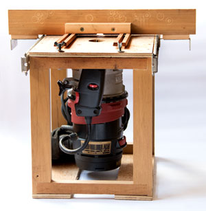
In the above video I show one I made to equip an old Thornton Pickard that I bought as scrap in Bièvres. The video is intended to discuss the project and show the outcome. The detailing of measures and construction tips are presented in writing in this post.
Building a camera back
Just as in the Linhof’s backs, which served as inspiration, the project followed a scheme in two basic pieces.
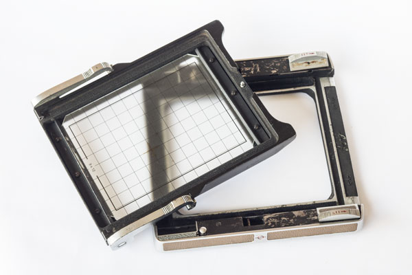
It is formed by a kind of frame that is part of camera body and receives another frame that contains the ground glass. At Linhof, the piece attached to the camera could rotate freely, at any angle, but that would be real luxury for a home-made project. Rotating 90º, on the other hand, is a very desirable feature to choose between landscape or portrait. Consider that in your project. The piece with the ground glass is constantly pressed against camera body by means of two springs. The film holder is inserted between the two as if it were a drawer and the springs hold it in position.
The base on the camera
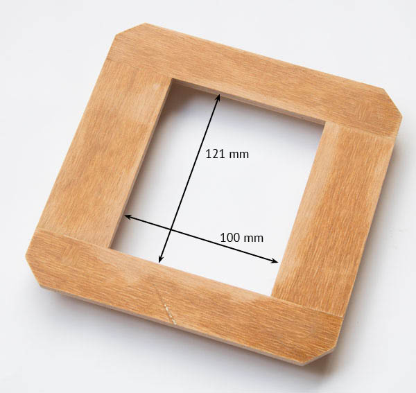
To build the base, start with 4 pieces of plywood from 4 to 6 mm thick. I do not recommend using MDF (Medium-Density Fiberboard) and the like. The plywood is more structural and stable. Arranged as in the photo above the four pieces should form a hollow frame in the center. External measurements should follow the size and design of your camera. The cut corners were required for mounting on the Thornton Pickard, will not be needed on other cameras. The internal measures follow the size of the window of your film holder and should be close to 4×5 “, remembering that one inch is 25.4 mm The holder for 9×12 cm has the same external shape, only the window is slightly smaller than 4×5 “. Therefore, the two formats are interchangeable with respect to the camera. But not about the film, each one needs to use sheets in the correct format.
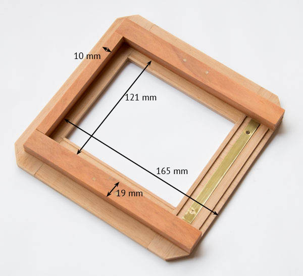
Next to this frame will be three pieces of wood that form the fitting of the film holder. They form three walls and leave a free side from which the film holder will enter. The external measurements are reasonably free but the internal ones must be precise, with the minimum of slack, for the perfect fit of the film holder. This is very important to avoid light leaks. I made it with 19 mm the slats on the greater side because they are the ones that will receive the two springs. The bottom lath is 10 mm because its sole role is close the bottom.
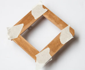
Considering the lack of precision of hand tools I have the policy that if two parts must fit together then it is better to fix them while fitted. I avoid doing it by measurements and hoping they will fit later. Following this principle I put together the parts of the base with tape, turned it, put the film holder in place, aligning the two windows well, and temporarily fixed it in place with small pieces of double-sided tape. Only then did I put the walls around it with a thin layer of glue. Taking care to not smear glue on the film holder. I tightly fastened it all with pressure clamps and allowed to dry overnight. This is what you see in the next photo and that guaranteed perfect fit. After drying, I put two screws in each batten so as not to remain depending only on the glue to maintain the structure.
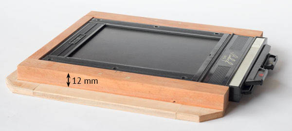
The height of the walls follows the height of the holders, around 12 mm. It’s not very critical. In the Linhof’s back, this wall is much lower and the whole thing is slimer. But I thought it best to make the walls rise to the same level as the holder in order to avoid light leaks.
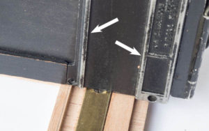
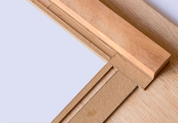
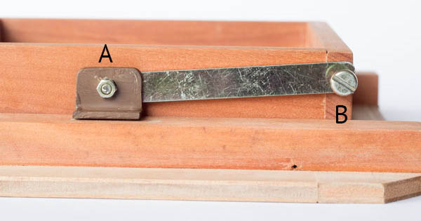
But before you fixing the walls, you need to prepare the base to receive the film holders. As mentioned above, they come in as if they were drawers, and the open side seal is made through grooves in which the two friezes, shown with white arrows in the side photo, (which is a Graflex holder) fit. In addition to light sealing these friezes have the role of preventing the holder from coming out of the camera the moment we pull the dark-slide, those friezes are the ones that lock the holder in its position in the back of the camera.
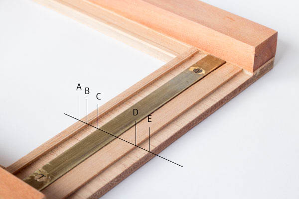
The distance marked AB, in the picture above, I made as 5 mm. At the back of the Linhof it is only 2.4 mm, however, considering that it is machined aluminum and in my case wood, I thought it would be better to give more thickness and contact surface. BC, is the recessed part with 2 mm depth. It measures 5 mm in length. C is the point where the film holder’s dent will anchor to prevent it from coming off unless it is lifted. CD measures 18 mm and serves to fit the second frieze. Note that point E falls short of the end of the film holder (clearly shown on the third photo above). This is important so that it can be securely grabbed to be lifted and pulled. Otherwise it would be very difficult to remove it from the back.
The brass piece, I put it in because I think that this edge is the one that will bear some friction and I was a little afraid that with the use it would end up hurting the plywood layer. I think it’s good to do a reinforcement in that part. But it can be made of aluminum, some plastic, acrylic or harder wood. One can also leave only the plywood and observe how it behaves. Perhaps it is too much of a precaution to reinforce this part.
Talking about reinforcing wood, improving its finish and preparing it for painting, it is very important that after cutting and sanding the pieces all receive several coats of sealer or primer. This impregnates their fibers making them as starched and sturdier. Makes it much easier to sand it before painting. I recently discovered and am using a natural substitute for the sealing synthetic primers . This is the rabbit skin glue. It is a “primer” used at least since times that go back to the gilding of sculptures and wooden furniture in the Middle Ages. I found it much better than the regular primers because it leaves the surface of the wood much better to sand. After drying it becomes very hard, it seals well the pores and shafts of the wood. Reminds me of shellac. It can be found in art material stores, fine woodworking and many online sources.
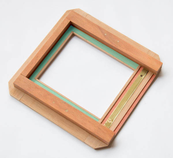
On recesses on the base, in addition to the recesses for the friezes of the holder, which should have a depth of 2 mm, shown with a red shading in the photo above, it is also necessary to lower it about 1 mm or less. That is the part shaded blue in the photo above. This edge will eventually receive a velvet ribbon, fabric or chamois paper and helps prevent light leaks. It is very important not to choose anything with thickness beyond the recess you have made so that the adaptation of the holder to the stop is perfect. It is best to go wrong for less and avoid any gap between the holder and the wooden stop where it will actually be supported.
The recesses, in the above part, were made with a handheld router adapted to a small table (photo on the side). This is a tool that only the most dedicated bricoleurs will have, so if that’s not your case, maybe you’d better take the pieces to a wood craftsman so he can do that part for you.
But I also want to mention another, simpler way of achieving the same effect. It is a question of “raising the floor” of the base in order to lower what needs to be lowered. This can be done simply with ruler, glue, blade and “leather paper”. Leather paper, also know as Chip-Board, used to make inexpensive guitar cases through the 90s (thanks to Sean who comment that on this post), is a material that is available for sale in leather goods supplies stores, those selling tools and materials for making handbags, shoes and wallets. It is sold in various thicknesses and is a very tough type of cardboard.
To use it, cut the 1mm thick leather paper and use two layers to produce 2mm recesses and only one where you need 1mm recess layer. Use white glue and glue one piece at a time. Then use a primer (or rabbit skin glue) and sand paper it thoroughly. The result is almost the same as machining the wood. The sheet is usually large but count that will make some tests before the final piece until you master the finish well. They are also great for making lens caps.
Frame for ground glass
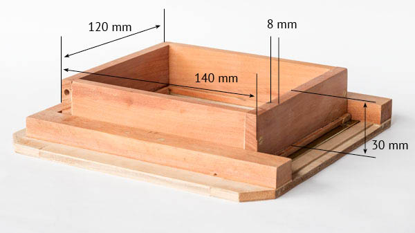
For the ground glass I made only one frame with slats of 30 x 8 mm, leaving it with external dimensions 120 x 140 mm. I used four screws in the center to attach to each other and form the frame. At the base of this frame a frame I attached 5 x 12 mm slats that leave a “tooth” into the frame’s opening. It is in this tooth that the glass will be rested (next picture).
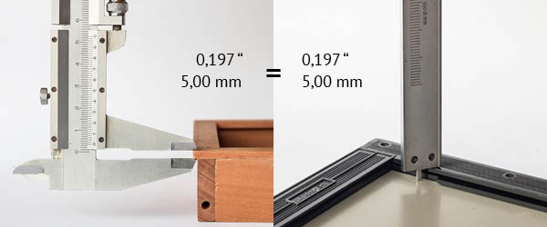
The most critical measure of the whole design are these 5 mm. This is due to the fact that this is the distance between the ground glass and the stop on the camera body (described above) and that it should be strictly equal to the measurement between the surface of the film and the holder. Assuring this equivalence we can trust that in removing the ground glass the film will come exactly in its place and the focus that was made in the ground glass will apply also to the film.
The best approach is to put a film sheet in your holder, measure it with a calliper and reproduce the measurement on the ground glass frame, or you can look for official measurements on the web. Be prepared to find different opinions. In the Large Format Photography Forum, to me a reliable source, you can find good threads about this subject. Including procedures to test your holders. I did both and happily found out that they match to 0.197″ or 5 mm. Also think that when you turn the rack gear of a large-format camera your hand should not even be able to advance in hundredths of a millimetre and your eyes will not see any difference in the image for displacements of that magnitude. Being good is already good enough.
In my case, I wanted to introduce an extra degree of freedom and cut the slats with 3.5 mm in height thinking of putting small screws in the inner part. With these screws I expected to make a finer adjustment of the height of the ground glass. Once done, I think it was over engineering. If I had just cut the slats with 5 mm that would be enough.
Bringing the two pieces together
The Linhof system is very creative and unintuitive. It uses two torsion springs to press the film holder against the camera body. The only difficulty in buying these springs is that the ideal case would be to have one clockwise and another counterclockwise, since they will be on opposite sides as we will see below. But you can do with two equal springs.
The photo above shows the metal part made to attach the camera body to the frame with the ground glass. B gets stuck on the latter and A on the first.
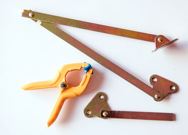
To make these pieces the easiest is to cannibalize household items or hardware found in hardware stores. In my case, I used clamps to get the springs and this window hinge to get the iron rod off. The L-bracket, painted with a brown primer, I did by cutting a piece of iron plate and folding it in a bench vise.
Axis B is just a bolt with a large head to hold the spring. Axis A is a little more complicated.
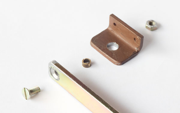
I used screw and nut in size M3 (quite easy to find). On the iron rod I made the hole with 3 mm and then widened to inlay the screw head using a 6 mm drill bit. It is necessary to hold the piece well to make these holes, a bench vise is advisable. In the L-bracket, the hole was much larger than 3 mm to accommodate the small piece that appears in the center in the photo above. It is a slice of a brass tube and its role is to allow the arm rotate freely in relation to the support, even by tightening the screw against the nut. That is because the tube slice prevents the support from being tightened as well. For this, the insert should be slightly longer than the thickness of the holder.
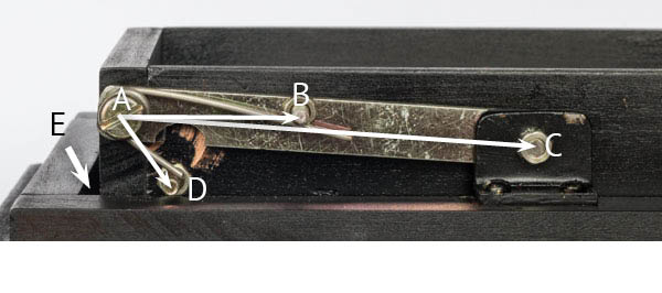
The AC distance was 70 mm, AB 31 mm and AD 14 mm. A gap was left between the ground glass frame and the frame on the camera body (marked E). This was to ensure the free up and down movement of the ground glass frame.
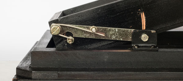
The first time I lifted the frame I noticed that the nut holding the spring hit the rod. I used a grinder to make a fit and to improve this movement. You can see in the photo that this fit was not very well positioned, but it was enough to insert and remove the film holders with ease. Another solution would be to place the screw hole holding the spring shaft higher. But this hole was already made and I thought that a second one would weaken the structure.
You can also see that the finish on the metal parts was not careful enough to keep them from scratching the paint. Next time I’ll be more careful. Overall, after mounted and painted black the back even lost some of the rustic look it had during construction.

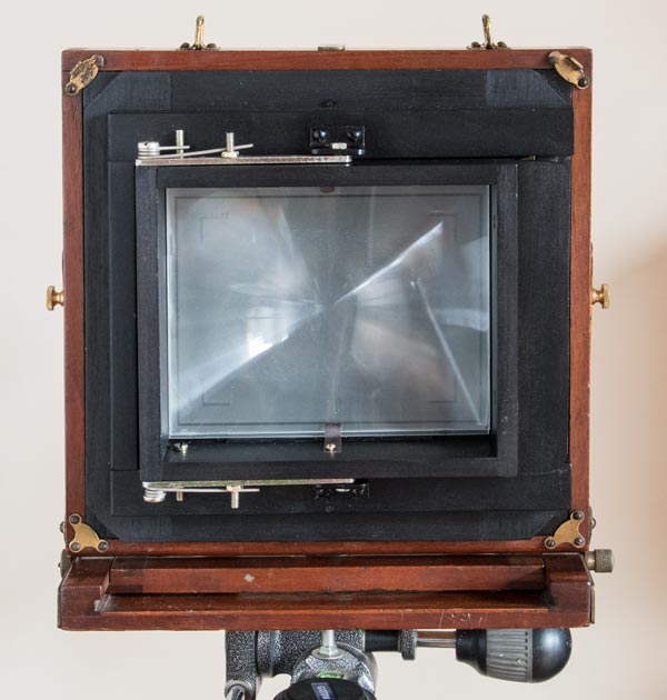
The ground glass and a Fresnel type lens (optional) are secured in place by means of two spring straps and two screws as shown in the photo. Always remembering that the order is: the grounded side leaning against the stop and looking at the lens. The grooved side of the Fresnel leaning against the polished side of the glass and showing its smooth side out of the camera. I added also a handle to easy the task of lifting the frame to insert or remove the ground glass.
After it was ready and assembled, I still did some tests before placing the velvet insulation that would enter the channels of the base. As there was no leak I decided to leave it without anything and I’m already using the “new” Thornton Pickard, both in 4×5 “and 9×12 cm, with some lenses that previously had no camera for them.
WOW! Beautifully done. I am working on a similar project and your pains in measuring and explaination are invaluable. My first try used an untested design from thingaverse as a template. Its off by quite a bit and scaled by X10 for some reason.
Thanks for a very detailed description.
Adapting my own build to accommodate spring mechanism described.
What is the diameter of spring wire and how many turns did yours have?
Mine uses a wire that is 1.3mm thick, and 2.5 turns.
Excellent! I build a back for Century 8×10 studio camera. I got confused, to understand the workings it is good to understand that A and D are the only fasten points that go through the GG frame.
I agree that it is not intuitive the work of springs and pivots. But it works great. I copied it from a Linhof camera back that I have.
This is what I was looking for. Having all the measurements in cm helps the new builder a lot. The question I ask myself is: which film holder can this project accept, in addition to the one you see in the photo. I think I will start the work immediately. Thank you so much.
It accepts the majority of double sided film holders for 4×5″ or 9×12 cm. Usual brands are Linhof, Fidelity, Graflex, Toyo, Riteway, Listo Regal, among others. Those are all standardized in their key dimensions. But in any case, I recommend you to start acquiring your film holders and making your camera back “around it”, like a tailor who makes a suit.
the depth of the ground glass should be 3/16″, not 5mm. 5mm is the depth of the septum/back of the film, 3/16″ is the front of the film/proper ground glass depth. obviously not a huge difference, but, you know.
Hello Michael, My reasoning on that is the following: since most of the people using this tutorial are not building film holders for sale, my advice is to measure their own holders and use that empirical measurement. When I searched on the web the official dimension I found 0,197″, close to the 0.1875 you mentioned (3/16) but not the same. For instance, in the Large Format Photography, Robert Zeichner quotes: “Z38.1.51-1951 is the American Standard Dimensions for photographic double film holders of the lock-rib type. “T” specs are as follows along with the tolerance for error. For 2-1/4 by 3-1/4, 3-1/4 by 4-1/4 and 4 by 5 holders the depth is 0.197″ and the tolerance is +/- 0.007″. For 5×7, depth is 0.228″ and the tolerance is +/- 0.010″. For 8×10, depth is 0.260″ and the tolerance is +/- 0.016″.” As I said in the post, I measured a couple of holders I have, like Linhof and Graflex and to my best estimate they matched these specs. Unfortunatelly, the link I put to a page with more details is no longer available so I just removed it. Thanks for your input. I will anyway leave the post as it is. To anyone reading this comment I recommend again: measure your own filme holders and use that measurement to produce your camera back.
I was lucky enough to inherit a Zeiss Ikon Tropen Adoro 230/7 camera along with a few film holders. Unfortunately, even though two of them are 12×9 film holders, they do not seem to fit the camera. I am dismayed that I cannot use the camera as the film holders don’t suit. However, the film holders are marked Zeiss Ikon 726/7 and the measurement shows a film size of 12×9. Then why dont they fit? I searched ebay for the suitable film holders that would fit my 230/7 camera but nothing turned up. Can anybody help me with a solution?
This are very hard to find items nowadays. The few that were kept are normally found with a camera. Finding just the holders demands a persistent and long term search. Try to find another Tropen Adoro with holders and negotiate one or two of them to be sold apart.
C’est un peu loin mais
https://www.alternativephotographicsupplies.com/Negative-insert-septum-9×12-cm-p125
Absolutely perfect instructions. Excellent work. Thank you for a clear, precise and to the point tutorial.
Hi! Great post! I love it that you are so open about this project, cause it is generally hard to fish something out in the internet about large format camera making that would actually be useful and well detailed.
I have one question though, could you share a link to the 1mm thick “leather paper” supplier. I am in need of this material at the moment for building my own camera back and a plate holder and it would be immensely helpful to get some of this stuff.
Unfortunately I can’t seem to find any in my hometown leather suppliers, so maybe you could share where you got it from.
Thanks!
Hello, I am afraid I can’t help with that. I am in São Paulo – Brazil. I doubt the store where I buy it would ship it internationally. But it is simply a very dense cardboard. It is used to give structure to purses. It is was used, in former times, to produce luggage and suitcases, that type with riveted metal corners. I don’t know where you live but for sure there might be something alike in your region. Maybe an art supply store will be able to suggest you something. Anyway, here is the link to the store called Marwal. This leather paper is under “papelão” section but it is such a “commodity” that they do not even specify different types and sizes . Marwal
It’s also known as Chip-Board and used to make inexpensive guitar cases through the 90s.
Thanks, good to know the name in English. I will include that info in the post.
Hi Sean,
it’s sold as “hardboard”, and comes in thicknesses of 1,2 & 3mm. Horrible stuff to cut with a handsaw, but tough & hardwearing, except at the exposed edges. I always seal the edges with cyanoacrylate glue (superglue) to harden them.
It’s STILL used to make inexpensive guitar cases by some Far Eastern manufacturers!
Hi,
Great article and a great website, thank you.
I am in the process of building a back for a large forma camera. You description and details of the spring mechanism are very helpful.
Hi!
Stunning! A complete guide! That’s what I sought for. Thanks a lot!
Hi,
very informative and might use this soon to create a back for a 5×7 camera, but two of the images are not loading on the page…
Thanks for posting!
Hello, many thanks for warning me about it. The broken links were like the images preceding them without the measurements. While posting I replaced them and forgot to erase the old one. Now it is OK.
Excellent explanation. Clear, precise photography. It took me a while to grasp how the Linhof torsion spring system worked–as you say, it is not very intuitive.Thank you for helping me understand this relatively hidden part of a view camera.
I have a ‘thornton pickard royal favourite’ that belonged to my great great uncle. I am restoring it and plan to shoot sheet film with it. It’s a 5×7 inch format with the original plate holders. Are there any ways to adapt a plate holder to hold sheet film. If you have any insights I’d love to hear from you.
Great information by the way. It’s helped me so much.
Olá!
Muito legal o seu vídeo no YouTube, também sou de São Paulo, estou muito enterressado em aprender sobre large format photograph.
Domingo irei até B&H para checar as câmeras. Sou totalmente novo no assunto, se tiver algumas dicas, será muito bem vindo.
Obrigado e parabéns pelo site.
Emerson Ader
Olá, Emerson, grato pela visita. Por enquanto, o que eu tenho de dicas é o que está no site e nos vídeos. Eu estou gravando um vídeo sobre Larger Format Photography, uma introdução, acho que até janeiro eu termino publico.
Good article, will try this on my 4×5 pinhole build. If you would have put a washer behind rod at “a” and moved “c” out same amount it would not scrap the paint. Also if you would have had a photo of the assembly before paint would have helped as it took me some time to realize that “d” was just a spring holder screw attached to the frame. All in all a great write up.
It is a good idea to insert a washer. My problem with DIY projects is that I always stop at workable prototype phase. If it does what it is intended to do, I normally leave as it is. I think also that I exaggerated on wood thickness, it could be a lighter structure… maybe next time. I will remember to better document it in photos.