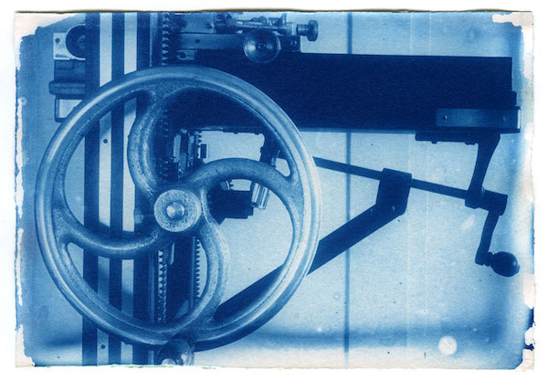
Solar UV print: Cianotype- from a dry plate 13 x 18 cm on Arches 300g hot pressed- formula de Mike Ware –
Cyanotype is perhaps the most popular UV, ultra violet, printing process. Without silver, low cost, it can be made on different types of paper and many other supports. Gum, too, is a low-cost UV process in which the color possibilities are endless. There is also Van Dyke Brown, Salted Paper and Carbon. Platinum and palladium are also UV-based, but even making them homemade, they cost more than commercial silver gelatin paper. All of these are historical, artisanal processes that form an enormous reservoir of photographic printing resources.
What is special about UV?
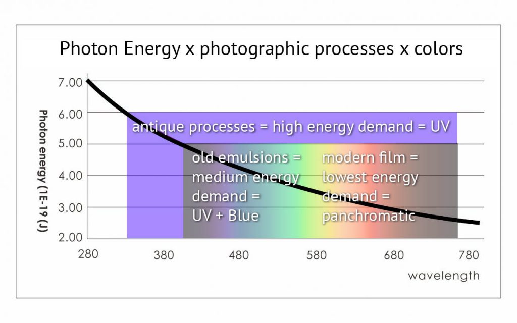
The history of photography can be seen as the conquest of the visible spectrum by photo-sensitive materials from the shortest wavelengths (UV, violet, blue) towards the longest wavelengths in the red region. The energy that each photon carries is greater when the wavelength of the radiation is shorter. In the Ultra Violet range, they are simply more “potent” than in the visible part of the spectrum. It was not a coincidence then that in the early days of photography processes emerged that were primarily sensitive to UV because their photons, being more energetic, are more likely to cause changes in materials. As the technology advanced, other colors were incorporated into the sensitivity range of photographic processes. With the UV came his neighbors, the violet and the blue. Soon after, green, which is more in the center of the spectrum. Only in the middle of the 20th century was it possible to reach the regions of yellow and red satisfactorily, which correspond to the “weakest” photons. Even so, this achievement was at the expense of emulsions that were still very contrasted and thus compressed the shades of gray somewhat drastically. The modern panchromatic film, with a wide dynamic range, capable of recording details in the shadows and in the high lights, this one came only towards the end of the last century.
Ultra Violet sources
For these printing processes that need ultra-violet light, the photographer has the option of using artificial light or sunlight. Artificial lights that really have a reasonable power and, more importantly, that reach the most efficient areas of the UV spectrum for these processes, around 365 nm, are expensive and more complicated to set up and power, especially if the idea is to expose large sized prints.
Outside the artificial lights, we have sunlight that is free, strong and rich in wavelengths in the good UV region. However, it is fickle and it is not possible to estimate how much UV is affecting the negative without the use of instruments. Even when comparing sunny days at the same time of the year and at the same time of day, the UV level varies because it depends a lot on atmospheric conditions. The UV level can vary even during the exposure of a single print if, for example, some mist or cloud enters or leaves the path of the sun’s rays. This may be imperceptible to our eyes but it can cause major differences in UV prints. That is, it is not possible to previously adjust the exposure by establishing only the time that the copy will be exposed, because unlike artificial light, sunlight has variable and unpredictable power.
Solar UV exposure meter
In this project you will build a UV Exposure Meter for sunlight that solves this problem once and for all. With it you do not directly choose a time, as if it were just a stopwatch, you choose the level of exposure that your photographic process needs. From there, after activating the UV exposure meter, it will monitor in real time the combination of time x UV intensity radiation, affecting its sensor, and will beep when the exposure reaches a pre-established level. You will be able to repeat the exposures, they will have different times but the same total energy. You will be able to make test strips and apply the results found later, even when the day or weather conditions have changed, as they will produce the same results.
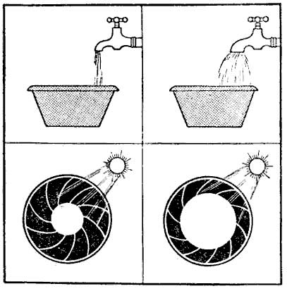
Thinking of the bucket of water analogy, often used to explain how aperture x speed are compensated in photography. This Solar UV Exposure Meter handles the sun as if it were a variable flow faucet and it gives the alarm when the bucket is full. You do not choose the time directly, you only choose how many “liters” you want, that is, the UV dose you need. The weather will vary according to the day, the hour and the atmospheric conditions, all of these factors that influence the amount of UV that reaches us.
Watch the video and get to know how it works. Below, find all the details for the construction of your Solar UV Exposure Meter. If you are not familiar with soldering and electronic assemblies, also watch the video Enlarger Head with LEDs, as there are several components used also in this project that are shown during assembly / soldering.
If you have no practice and do not want to learn how to assemble yourself, know that this project is very simple and certainly in your city there must be someone tuned in to this wave of robotics and the like who can easily assemble this UV exposure meter for you. Search for the keyword “Arduino” in your locality and you will find someone. Arduino is the name of a family of microprocessors that are moving a legion of young people, others not so young, for projects of this type all over the world.
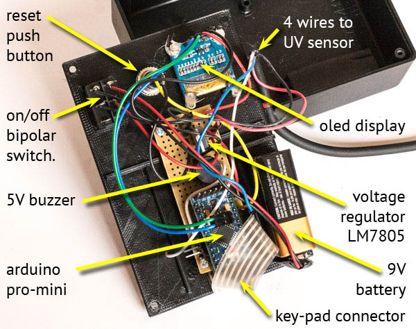
Inside the Solar UV Exposure Meter
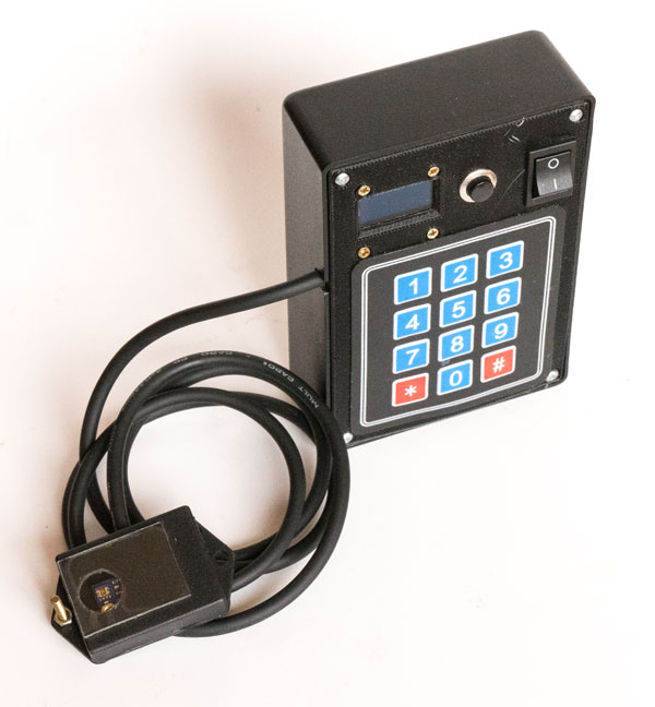
Above we have the control box open. It basically has a membrane keyboard of which you can only see the tape with 7 tracks e connectors, an Oled display and the Arduino Pro Mini 5V microprocessor. The photo above is of the prototype that I made and that I’m using. Once ready I discovered an easier way to pass the wires by connecting the keypad on the other side of the Pro-Mini. If you are very observant you will notice this and then I am warning you: yes it is different from what is shown below.
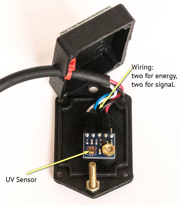
Following is the ML8511 UV sensor. It is convenient that it be mounted in a separate box as it will obviously be out in the sun, but it is not practical that the control box is also exposed. It will be better for its conservation and also to facilitate the reading of the display, so that it stays in the shade. The long screw with nut seen in the photo below is only used to direct the sensor towards the sun. When the screw does not cast any shadow on either side of the nut, it means that the sensor is receiving direct sunlight.
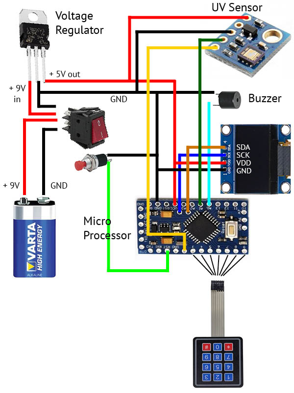
Circuit
For someone like me who has no practice in reading circuits through symbols, I think it is easier to have a circuit with pictures of the components as shown below. Note that the components are totally out of proportion to their sizes.
Bill of materials:
Microprocessor Arduino Pro-Mini 5V
UV Sensor ML8511
Display OLED 0.96 inches
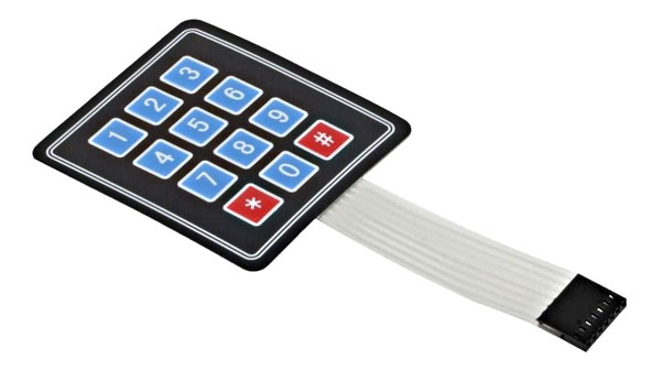
Membrane Keypad 3×4
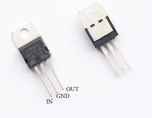
Voltage regulator LM7805
Main Bipolar Switch – on/off
Push Button (Reset)
9V battery with terminals
1 meter cable 4 wires
Boxes for control and sensor
Male/Female PCB terminals
Standard PCB (printed circuit board)
Assembly
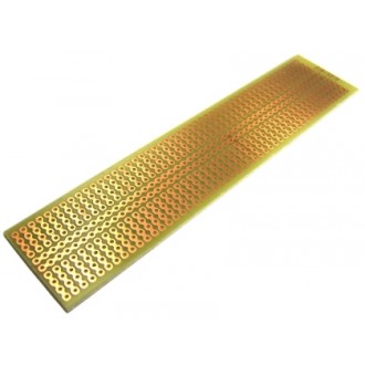
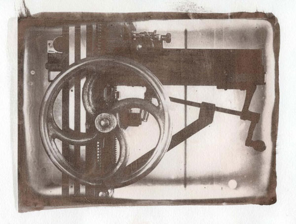
To assemble, buy a standard printed circuit board like the one in the photo below or similar. They typically have two long longitudinal tracks and two groups of four-hole tracks in the cross sections. The Pro-Mini needs a row of 12 holes. Cut the board around 20 holes and it will be enough (see the picture of the open box to understand)
Next I will give a sequence of connections. Make a plan before you start soldering. Study the length of the wires so that they are not left too much and that they are not missing so you don’t have to make amendments.
To assemble the Pro-Mini you need to solder both male and female PCB connectors (printed circuit board). Females go on the PCB and males on the Pro-Mini (see component details below). Two rows of 12 female connectors will receive pins from the Pro-mini. A row of 8 males, positioned and connected to pins 2 to 9 on the Pro-Mini, will receive the keyboard connector (3 to 9) and a UV Sensor connector on pin 2.
Solder the LM7805 by taking 3 groups of 4 holes at the other end of the board, opposite the Pro-Mini
Connect the wires from the battery connector to the double switch.
In the holes connected to the IN and GND of the LM7805 (see below how the LM7805 pinout), connect the battery positive to the IN and the GND to the negative of the battery. But remember that these wires coming from the battery are going through the switch. The LM7805 will be switched on.
The two long tracks we will use as the main GND and + 5V supply. They will be the device’s power line. It will be used to power the UV Sensor, the Buzzer, the Display and the Pro-Mini itself. Then connect the GND of the LM7805 to one of the long tracks. Connect the other long track to the OUT of the LM7805, this is the + 5V. Make a mark to make it clear who is who between + and -.
Connect a wire between the positive track and the Pro-Mini’s VCC pin. Connect a wire from the negative track to the Pro-Mini’s GND pin.
Weld the Buzzer with the shortest leg (negative) on the long negative track and the longest leg (positive) in any group of 4 holes. Choose one of the remaining holes in this group and wire it to the four-hole track that has the Pro-Mini pin A0 (A zero). This is the pin that will make the Buzzer sound.
Solder two wires to the push-button that will be the reset that resets the Exposure Meter. One of these wires must be soldered on the long negative track, anywhere you find convenient, and weld the other on the track where the Pro-Mini’s RST pin is.
To logically connect the display, the most practical thing is to make jumpers or buy ready-made. Pin A4 of the Pro-Mini goes to the SDA of the display and pin A5 to the SLC or SLK of the display.
To connect power to the display, pull one wire from the positive track to the VDD of the display and another wire from the negative track to the GND.
It is best that the UV Sensor four-way wire has female terminals on both sides on the four wires. Note which colors you used for VIN, GND, OUT and EN. It has also a 3V3 pin that will be unused. It serves to energize the sensor with 3.3 V circuits, which is not the case as we are using 5.0 V.
At the other end of the wire, connect the VIN to the 5V positive long track and the GND to the negative long track. The OUT of the sensor goes on pin A1 of the Pro Mini and En goes on pin 2. If you did not place female terminals on the ends of these wires, you can weld these tips directly on the board. Otherwise, which is better, you must have left male pins on the board and then just plug these wires.
Plug the keypad connector into the row of male pins corresponding to 3 to 9 on the Pro-Mini. See bellow details about the keypad wiring.
It doesn’t matter how you assemble, the box you use, with an external sensor or built into the box itself, or even everything loose and without any box. If the connections are made according to what was said / shown above, all you have to do is upload the program in order to use the UV Exposure Meter. It is possible that after a first montage your vision changes and you notice a much better way to position things. So it is good to buy an extra PCB and some extra connectors to be able to make these improvements.
Knowing the components better
The following is a description of each component and more details that you should know before starting to assemble.
Arduino Pro Mini Atmega328 16mhz 5v
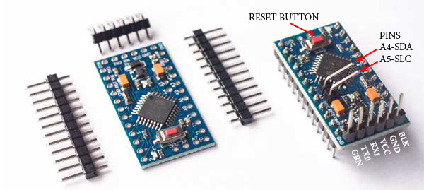
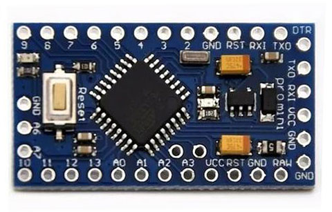
Arduino Pro-Mini Atmega328 16mhz 5V – this is the microprocessor, it is the intelligence that will control everything. I believe that to occupy less volume it comes without the pins, as seen in the Pro-Mini on the left. The first step is to solder them and make it like the one on the right. Start with A4 and A5 in the middle of the board. Then the order of the other three combs is indifferent. The big ones are the pins that the Arduino uses in its normal operation and the ones that are on the smaller side: BLK, GND, VCC, RXI, TX0 and GRN, are for communication. It is for the latter that the program is loaded. Note that the large combs are with the pins down while the communication pins are up. I don’t know why pins A4 and A5 don’t come in the package with the card. You need to buy singles. Once prepared in this way the Arduino can be plugged and unplugged from the board.
Sensor UV ML8511
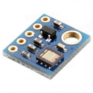
The ML8511 UV Sensor may vary from manufacturer to manufacturer. There is usually an original that was developed by a large company and then there are many clones on the market. The sensor itself is just that little square piece that appears in the bottom corner of the photo. But it is sold on small boards that facilitate assembly and connection and includes some protections.
It is evident that you need to leave the sensor exposed to sunlight and therefore, if you set it in a small box, this one must have a window. A window covered by a small piece of glass is a good idea for protection against dust. Do not mind the UV loss caused by the glass as it is small and also its sensitive material, once placed in the contact print, will also be under glass.
What really matters about the Sensor is its response to UV radiation. It is shown in the following charts from ML8511 Datasheet.
The first graph shows that it is very linear over a long region of different intensities and that it does not vary significantly with the ambient temperature. The second shows where the sensor is more reactive. Note that it has a peak right on the most interesting part of the UV spectrum, when it comes to photographic processes like Cyanotype, Van Dyke Brown, Goma and others. This sensitivity peak is at ~ 365 nm.
It is manufactured for applications related mainly to health and therefore it is calibrated to respond precisely to solar radiation. For use as an exposure meter in photography, there must be sun. Scattered, passing clouds, fog, early morning or late afternoon sun, are not a problem, however, on a really cloudy, dark day, with little UV, the times it will ask begin to get too long and erratic for normal doses that photographic processes call for.
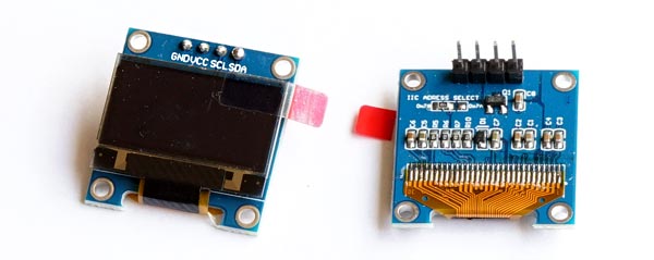
Display Oled 0.96 Spi
The display uses only 4 pins as it works with the I2C protocol for communication. The SDA and SLC pins are connected to pins A4 and A5 of the Pro-Mini, respectively. The Vcc pin is connected to + 5V and GND, ground, goes to the negative track on the board. This order may vary from one manufacturer to another. Check yours. Also keep in mind that after screwing the display onto its bracket, you will probably no longer be able to read the pin marking. Write it down before you fix it.
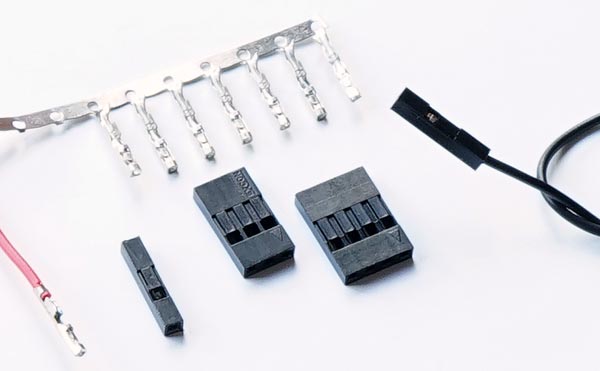
Jumpers
You will need to prepare some wires with terminals to connect the display on the Arduino. There are jumpers that are wires with a terminal at each end but they are fixed in size and the wire is generally very thin and of poor quality. I prefer to buy separate wire and terminals and make the jumper with solder and in the size that I will really need. In the video of the enlarger head using LEDs I show how I do it, I don’t know if it is the best way, but it is easy and after some practice it is quite satisfactory.
L7805 voltage regulator
The voltage regulator is very intuitive. There are three pins: GND must be connected to the general GND as the ground is common. IN receives + 9V and in OUT we have + 5V connected to the Arduino Pro-Mini. The display, the buzzer and the UV sensor are also 5V. The maximum current that the LM7805 can withstand is 1.5A, it is not much but it is more than enough for this application.
Keypad
For this project, a self-adhesive membrane keyboard is ideal. It already comes with a ribbon and female connectors that you can plug directly into male connectors soldered on the board and corresponding to pins 3 to 9 of the Arduino. There are two groups, one of 3 and the other of 4 connectors corresponding to the 3 columns and 4 rows of the keyboard. Each time a key is pressed, a pair of terminals is short-circuited.
I cannot guarantee that there is a standard in the way the keys are connected by different manufacturers. The following explanation worked for what I set up. With the keyboard in the above photo position, the connector on the left is number 1. From 1 to 4 correspond the rows, from top to bottom, from key 1 to key *. From 5 to 7 are the columns from left to right. The program you are going to load is written for this configuration. Pin 1 on the keyboard is connected to pin 9 on the Pro-Mini and the rest follows.
If by chance, after everything is ready, the numbers you enter do not correspond to those that appear on the screen, no panic, you should just change the order in which these pins are referenced in the program, there is no need to fix this on the wires themselves. See below in configuring the keypad.
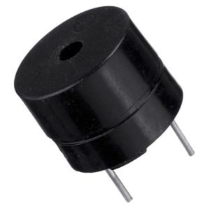
Buzzer
Buy a 5V buzzer that can be plugged directly into the board. There are several sizes but this one, which has approximately 7.5 mm between the pins, is one that occupies exactly 3 spaces on a standard plate. Also pay attention to polarity. The positive goes on the Arduino pin and the other on the negative of the circuit. Unless specifically stated otherwise, the largest pin is the +. If you reverse the polarity it will not work.
Battery, switch and push button
The 9V battery is well known. Be sure to also buy its standard connector. For the rest you will need a bipolar switch to completely disconnect the battery from the circuit.
Attention to the Reset Push Button. There are buttons that are normally on and go off when pressed. What we need here are the other kind, the ones that stay off and go on only when pressed. This is described as NO, normally open, or NC, normally closed, normally closed. Reset needs a NO, check this before buying.
Sketch, upload to Pro-Mini
The program that controls the entire operation of the Solar UV Exposimeter is called in the Arduinolandia language sketch. I will try in this tutorial to make it so that someone can blindly load the program on their Pro-Mini without knowing anything about programming. If you know something, but not Arduino, I can warn you that the code in which the sketch is written is like C ++. In the file apenasimagens_solar_UV_exposure_meter_en.zip I included “useful links” and there you will find a series of links to go deeper into Arduino projects. I think it is very worthwhile for analog photographers. My lab is full of timers, sensors, heaters, coolers, dryers and other gadgets made with Arduino.
Even without knowing how, at least knowing what you are doing is important. So here are some explanations:
The sketch is written in text form. There is specific editor called IDE which is downloaded for free for MAC, PC and Linux platforms. Do a search for Arduino IDE and you’ll find download options.
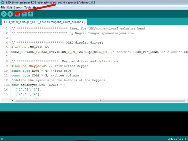
The sketch for this project is in the file apenasimagens_solar_UV_exposure_meter_en.zip and is called apenasimagens_solar_UV_exposure_meter.ino. After hitting file> open and opening this .ino you will have the following screen (the sketch below is another one, just as an illustration).
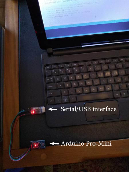
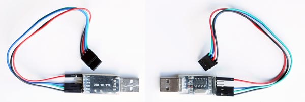
After loading the sketch you can connect the Pro-Mini to the Serial / USB interface (you will need to buy one, if you don’t have it), following the indication of the cables, remembering that the TX of one goes in the RX of the other and vice versa , VCC with VCC and GND with GND. Plug it into your computer. I use a very old lap-top, with Windows XP, exclusively for lab stuff including the Arduino IDE. It is more so as not to throw it away. Since I do not connect it to the Internet, it does not receive garbage, and it will probably last as is for many years. As you soldered the pins on the Pro-Mini, the names may have been hidden a little under the terminals. Use the photo below as a reference of where are GND, VCC, RXI and TXO. They are on the right edge in the photo below Next, a typical serial / USP or USB to TTL interface, in detail, front and back. The wires are already arranged to plug directly into the Pro-Mini following the pattern of black – and red +.
Although it is physically connected, it is necessary to check if they are connected logically. That is, if they “realized” that they are connected. The IDE is prepared to handle several variations of the Arduino architecture. You need to say which one is yours. Go to the menu and click Tools> Board and choose “Arduino Pro or Pro Mini”. Then go to Tools> Port and see if the IDE has assigned a port for me Pro-Mini. It must be COM followed by the port number. If no COM appears, try unplugging and plugging in the Serial / USB interface again. This usually does. If a COM has appeared, click on it. In the bottom right corner of the IDE window you need to check if it is the Pro Mini that entered and if the COM marked is the same as the one you clicked and that you see in Tools> Port.
I remember that the first time I did this on my lap-top I had to change something in the Windows configuration so that it could read the interface. But that must be dependent on your operating system, your computer, the particular interface … in short, computer stuff. In the file apenasimagens_solar_UV_exposure_meter_en.zip I indicate some tutorials where you can solve this type of problem if it happens.
Once the physical and logical connections are made, just click on the button that is the arrow indicated in the screen shot above by the red arrow. The download process will start.
But before clicking, an important note. This sketch calls some libraries, with extra instructions, that hold functions used by it. There are two, in this case: 1 – The library that drives the display is called by the following line in the sketch: # include <U8g2lib.h> 2 – The library that drives the keypad is called by the following line in the sketch: #include <Keypad.h> These libraries are used a lot and are normally loaded in the installation of the Arduino IDE. However, if you give the order to upload the sketch and these libraries are not present in the IDE you will get an error message. In this case you need to include them manually. Go to Sketch > Include Library> Manage Libraries and follow the instructions. There is no harm, it does not cause any damage, if you test the upload without knowing whether the libraries are there or not. It will only give an error message. Perhaps, by the time you are reading these lines, there is already a new IDE that, in case you can’t find it, automatically search for the online library and install it for you.
This operation can be done with the Pro-Mini plugged or unplugged on the main board of the control box (in the photo above it is outside, for example). But if it is in the box, do not connect the 9V battery as the USB interface already powers the Pro-Mini.
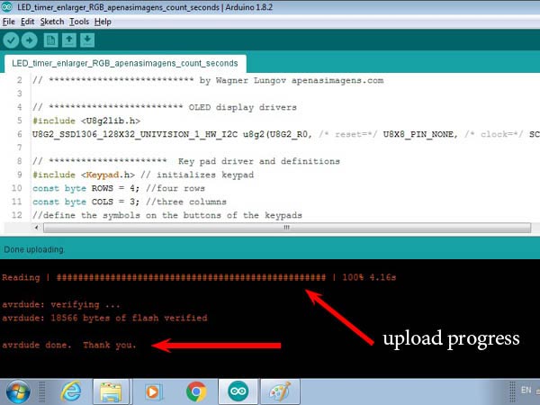
When you click Upload (arrow indicated above), on the IDE screen, the code will be compiled first. Sketch’s friendly text will be converted into hieroglyphic machine language and there will be a check for more coarse errors such as syntax, if the functions and called libraries are available and things like that. It takes a while but everything should be fine.
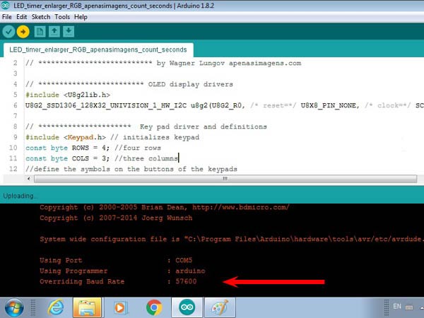
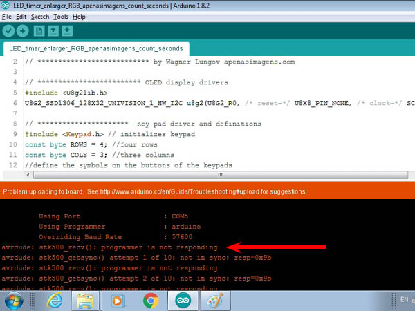
When the Pro-Mini was connected to the Serial / USB interface and both to the computer, it is powered up. It is already started and running a program called blink.ino that makes a led associated with pin 13 turn on and off every second. The microprocessor will be busy doing this and doesn’t know that you’re trying to load another, much more interesting sketch. So, when the sketch is ready to download from your IDE, you need to press the RESET on the Pro-Mini, it can be the RESET on the control box, if it is there, so that it stops with Blink and starts to load solar_UV_exposure_meter.zip.ino. Otherwise the Pro-Mini will simply ignore your upload attempt. The exact time to hit RESET is a little tricky for beginners. Keep an eye on the computer screen and finger on the RESET while the IDE compiles and checks. It will write a few lines on the screen and at a given moment it will be written: Using Port: Using Programmer: Overriding Baud Rate: This “Overriding Baud Rate” I think may not come because perhaps IDE will decide not to overwrite its Baud Rate. At that time you press RESET. If it was the lucky time you will see a progress bar made up of ##### indicating that the program is being sent to the Pro-Mini. It is very fast. It will end with a Thank you. In case something went wrong, if you missed the right moment, you see see the following: The IDE will try 10 times to upload. Theoretically it is still possible to have the luck of pressing RESET at the right time, during these 10 attempts, but I almost never managed to get this good moment right and so I adopted the procedure to wait for the 10 attempts to fail and start again by clicking upload in the IDE.
A first test you need to do is to see if the numbers you type appear correctly on the screen. If not, you will need to change one line in the sketch. Below is shown where this should be done.
All right, at that time you remove the Serial / USB interface and, if not already, plug the Pro-Mini into the main board in the control box. Congratulations, now you can start monitoring your exposures with your Solar UV Exposure Meter.
Keypad sketch configuration (if needed)
I believe that 4×3 membrane keyboards are all the same and should work properly if you connect everything as shown above. However, just in case, here are instructions on how to proceed if for any reason you need to reconfigure. If you have problems with numbers on the display that do not match what you are typing, follow the instructions below.
Open the sketch in the IDE and find the following block of text:
// *** the following line relates and configures the keypad with the pins 3 to 9 in the Arduino Pro-Mini // in case you see different figures than the ones you type in the key pad, it is the order of these // figures that must be changed to fit in your keypad byte rowPins[ROWS] = {9,8,7,6}; byte colPins[COLS] = {5,4,3};
The first curly brackets in the last line indicate that the rows of the keyboard correspond to pins 9,8,7,6 of the Pro-Mini and the following the columns to 5,4,3. These will always be the numbers if you assembled it correctly, but perhaps in another order. Try reversing one or both blocks. See if any documentation came with your keypad. Try other combinations and sooner or later you will find the one that works.
Changing the sound warnings
In case you want to change the way the Exposure Meter beeps you can do it at the end of the sketch. Sounds are called by two functions defined as:
done() is played when the Exposure Meter gets ready do start working (line 69 in the sketch) and at the end of an exposure (line 128)
beep_b() is called several times, at the initial countdown and whenever a key is pressed
The command digitalWrite(buzz,HIGH); turns the buzzer on and it remains on until a digitalWrite(buzz,LOW) is issued. After digitalWrite(buzz,HIGH); I inserted a delay(t) before the digitalWrite(buzz,LOW) and t becomes the time the buzzer is on until it is switched off. That is: t is the duration of the tone.
If you want, you can play writing your customised tunes with a sequence of lines like this:
t_on is the duration in milliseconds of a tone played by the buzzer and t_off is the time in milliseconds that it will be in silence until the next sound. Of course you don’t need to set duration for the last pause.
Once you are done with your sequence of beeps and silences you can overwrite the sequence I wrote. Insert it into the curly brackets that define the functions done() and beep_b().
If you want to change also the instances when these sound signals are called, then you can do it at your own risk.
Finals
I am publishing this tutorial more than a year after having built my Solar UV Exposure Meter that you see in the photos in this post. Since then I have been using it regularly and my experience is that the results are very consistent. According to the process and according to the density range of the negative, I have already noted some values for exposure and processing that I can repeat among similar negatives. That was the goal. I can also do a test strip in the morning and print only in the afternoon with the confidence that it will work the same. I’ve had several UV light printers but none of them seem to have the rich wavelengths that sunlight has. The highest densities and the richest tonal ranges depend on the light source being well in tune with the sensitive material used. So far I haven’t seen anything that is better than sunlight.
If you find something obscure in the tutorial, something difficult to understand or something wrong, please write to me and I will see what I can do to correct or improve it. I’m just not going to answer questions like “where did I go wrong?” as this would imply analyzing the execution of your project in particular. I also have no interest in manufacturing and selling these devices and I even encourage you to do so if you feel like. I have seen a growing interest in these historical processes, using UV, and I believe that a photography school, or someone working in the area, with a disposition for the thing, could very well offer devices or kits for assembly as a side business. My collaboration comes only so far and consists of making this knowledge available to anyone who wants to learn, use and improve it.
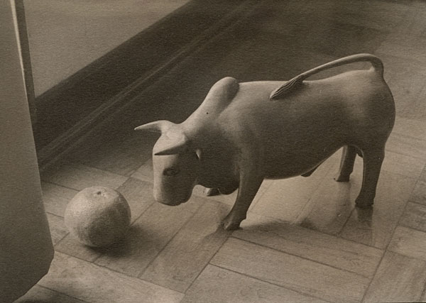
UV printed: Gum Bichromate from Dry Plate single coated (13 x 18 cm)
UV printed: Van Dyke Brown from film negative Fomapan 100 (13 x 18 cm)
UV printed: Van Dyke Brown from film negative Fomapan 100 (13 x 18 cm) –
END-OF-ARTICLE-CHECK
79 Comments
I’d like to make this UV meter. Is there a parts list somewhere? I’m lost. Thank you for sending me some instructions as to what to buy and where to buy it.
Just want to chime in with another thank you for sharing your build, Wagner. I am making my own at the moment, and wouldn’t have done it without your inspiration. Thank you!
Hi Walter, subject: Cant add your file to my library.
I have Arduino IDE 2.3.2. and run Windows 11.
– I downloaded your file: apenasimagens_solar_UV_exposure_meter_en.zip in my download folder.
– I proceed to add it to my Library: Sketch>Include Library> Add .ZIP library… , selected your file and click Open.
– The response I get from Arduino is:
Error: 13 INTERNAL: Library install failed: archive is not valid: multiple files found in zip file top level
– I tried to remove files in the.zip files that are not essential (the MAC and the 2 pdf), just keeping the .ino.
– I get another error message.
– I tried without and with my Arduino board connected. Same error messages.
– I closed IDE and restart it: same error messages.
– I rebooted my PC and reopened IDE: same error messages.
Do you have an idea why I have this? I am able to install files via the Library Manager.
Should I just try to copy the .ino file and copy it into a new Arduino sketch? I would prefer to use the ‘proper’ way but it does not work…
Can you help? Thanks!
The file I made available is not a library. That is why you are getting errors. A library defines functions to be called from a sketch, mine is simply a sketch. Inside my .zip you will find apenasimagens_solar_UV_exposure_meter.ino, you just have to open it with file>open with the Arduino IDE and upload it to your micro processor. Hope this helps.
Hi
Thanks for publishing this. My daughter is making a lot of cyanotype and Van Dyke Brown prints but is using a UV light box. She discovered that there seemed to be variation in the output of her UV tubes and referred me to your developement of the UV Exposure Meter.
Inspired by your article, and sketch, I made a variant for her using components from Adafruit and Sparkfun. I had to make a number of alterations to the sketch to accomodate the various components and UV sensor that I chose. My daughter is now using it and is very happy with the result.
My question is more out of curiosity than anything else.
In the line of the sketch:
float const conv = .003787878; // *******************************************conversion factor
How did you obtain this conversion factor and why is such a high level of precision required. For example conv = .004 as a conversion factor would not be quite as precise but in the end would make little difference to the calculation.
With the UV sensor that I used and my daughter’s equipment we had to modify the constant to conv = .02 to get input numbers and times that worked for her.
Hello, good to know that my project is inspiring new versions and adaptations. The factor is just introduced to make up for a sort of background noise from the sensor and set the scale to more friendly figures. It is reasonable that with different hardware this adjustment must be adjusted to a new value. You are right, there is no need of such precision. I think I just made some calculations and copy/paste the result there.
Hi Peter, can you share the components you use? I am particularly interested in the UV sensor you are using, but any other info on the parts you used would be appreciated! I am using both a LED UV and the sun, when it shows up, here, up in Québec…
I am having difficulties finding an ML8511 and I thought I could try the Wave 20467 which is based on the LTR390-UV-01 sensor chip which, if I read correctly, can read wavelength from 280-430 nm with a peak at 300-350 nm.
And thanks Walter for all this excellent information!
Thanking you both, Jassy
As others have already mentioned here, thank you very much for all of the time, and effort, that you put into this project, and for sharing it!
I have read your text three times. I have watched your video three times. I have read all of the questions, and answers, related to this post twice. I have a few questions to ask of you. I have written them in a way that you can answer them (If you choose to!) with a “yes”, or a “no”. (I do not want to take up much of your time!).
1) In your video, you have your exposure meter setup in an example that has sunlight (UV light) passing through large windows to an interior setting. In studying that portion of the video, it is evident that you appear to be in a city setting, and that you don’t have convenient access for exterior use. When the “buzzer” sounds, you can hear it and are close by to stop the exposure of your print.
I live in a rural setting; the state of Maine, USA. Because I live in a cold climate, the windows in my home are small to conserve interior heat. But, I have easy access to the outdoors and abundant UV light. While I wait on an exposure, I would be working on other projects; where I would not be in the vicinity of being able to hear the “buzzer” go off.
Question: Is there a way to trigger a remote sound; possibly by integrating a WiFi option?
(The simplest solution that I can think of is to, locate an outdoor security camera near the exposure meter that has the ability to transmit a visual and audible signal to an app on my iPhone. I already use these in my home in an application where I have a camera pointed at the readout screen of my Freeze Dryer unit. I can “go about my business” during a Freeze Drying cycle – fruit and vegetables – but monitor the progress on my phone.).
2) Your project is a very useful one! If I understand its capabilities correctly, it is essentially a “data logger”; capturing the sum of UV exposure. While your project is much less expensive to make then purchasing a “ready made” UV data logger (Used in museums, etc.), the build process may be intimidating to many who would see the great benefits of owning one. This would include me…..
Question: For those individuals who would like to own/use a device like your UV exposure meter, but lack the skills/tools necessary to build it, is there a way to “cobble together” two, or three, “off-the-shelf” units that can achieve similar results?
In essence: If you take this item (Already built), and that item (Already built), and “connect them together” with this item (Already built), you will have a similar exposure meter as the one that you have produced. My thought is, something like this may make a wider “audience” successful in building their own exposure meters.
Thank you again for all that you have done for our community!
Fist of all, very sorry for the delay in answering you. Normally I receive an email prompting me about comments. But I recently changed my email do a gmail.com and now I realize that it is not working. I will switch it back to the lungov.com email.
1) to your first question. The Arduino beep is activated by a pin that goes from O to 5V. One can use that logical signal to trigger many different things. By using a relay, even high power devices can be activated, like a louder buzzer. The logical 5V Arduino provides is only capable of activating a quite buzzer. Using another micro-processor (I have used ESP32 in some projects) you can easily send a signal, via wifi, that could do something on you mobile phone. I don’t know your level in dealing with these electronic stuff. But is perfectly possible to redirect the pin that activates the buzzer in the original project to do something else.
2) I think this project is the simplest way to “integrate” or accumulate the UV load over a certain period of time. It has the minimum that is needed: a sensor, a microprocessor, a buzzer, a screen, a keypad (these last two could be replaced by a mobile phone by using a microprocessor with wifi capabilities).
My advice for those not willing to try out soldering and assembling a project like this is to get in touch with the community of people doing robotics. Many youngsters are crazy about Arduinos, and the like, and keen to go beyond the boring projects like lighting up an LED or writing “Hello World” on the computer screen. Maybe a search in Forums with Arduino as key word will help you to find someone to partner with.
Great idea. This is “almost” exact device I need. Almost as I would like to use it for wet collodion.
So. My idea would be to extend range of light detected into visible blue with RGB sensor add to the system (only blue channel).
I wonder how easy would be to modify the code to use combine results from two sensors for a full spectrum that wet collodion can see.
Fist of all, very sorry for the delay in answering you. Normally I receive an email prompting me about comments. But I recently changed my email do a gmail.com and now I realize that it is not working. I will switch it back to the lungov.com email.
Using a second sensor, as you said, you can just repeat the same structure in current code using another pin for reading the blue channel. Some lines below you can add the UV and blue signals and use that sum in the countdown aiming a combined load. I would just add different weights to each channel in order to be able to adjust how collodion respond to these different wavelength regions.
But, thinking while writing, it is also very possible that using only blue or only UV you could get the same result. That is because, maybe, just one could be used as an indicator of the other’s presence. Only in the case of significantly different balance of UV x Blue in the solar spectrum, the separated detection of both could be of importance. I would go first with just one of them and expect for consistency.
In relation to the question of noticing a signal even when completely blocking light : I must assume that this is what is called “black current” in scientific light detection instruments; and, Oh Yes, we’re not dealing with ‘current’ here, but with a voltage, but the principle remains the same, I guess. If you look at Wagner Lungof’s IDE program, it mentions a factor called “uvLevel_shift” in line 27. It is set there as 200. Playing with this value may allow you to set your reading value to “0” when no light hits the sensor. In principle you could write a short sequence in the IDE program to measure this “dark current” voltage and have it automatically set back to zero each time you switch on the meter – but that’s entirely up to you.
The issue I have is that the reading out is rather fluctuating (high noise level), and even when adding a more elaborate version of 5V regulator, it still behaves the same. Somewhere, I heard that the 5 voltage that comes out of the Arduino is rather unstable – and the 3.3 V output is a lot more stable (<1% variation). I have no evidence to confirm this statement however. If 5 volts would be needed for the UV board, there should be a way to use the 3.3 volts output of the Arduino to act as a "reference" value, so you could use this to correct the output from the sensor fed by the 5 volts (by reading both 3 and 5 volt outputs and with these readings create a correction factor for the UV sensor value). I sincerely hope I'm not making any big mistakes here, but I hope someone who knows more about this topic and is fluent in IDE programming could help out here! In any case : Thank you Wagner for sharing this project and thanks to all the folks who commented with relevant questions and answers. Have a nice day to all.
Yes, you are right Walter. I wrote this code in 2017 and did not remember that I actually had to introduce a curve shift in order to get figures in an interval in which no UV would read close to zero. I completely forgot that, but I also had to deal with that kind of parasite voltage. Thanks very much for your contribution.
Firstly, a *massive* thank you for posting this wonderfully detailed project! I have now constructed my own version using your instructions and am having a play with it before deploying for wet plate collodion photography.
A question if I may – when I cover the UV sensor completely, the base level of UV readout only drops to around 110 on the display, and hence if I set an exposure amount of perhaps 030 like in your example, it will continue to count down the seconds until it believes a full dose of UV has been received – I’ve tried playing around with various values in the code, particularly the offset and conversion factor, but I wonder if you could give any advice please?
In my meter, if I cover the sensor, the UV level drops to zero. Things you can check about it: Are you using the sensor specified in the tutorial? Is it fed with the right voltage? Most of the problems I faced developing projects with Arduino family micro processors came from a bad quality power supply. Of course you have to re-check your connections. Several times I had problems and only when I started doubting the obvious I eventually run across a solution. Sorry for the late answer but I was traveling and returned this week.
I’ve successfully created a breadboard version of this project, although slightly reduced in functionality at the moment (no switches and no buzzer). I am excited about continuing forward and creating an enclosure to be able to use this in the field. Having never soldered anything before a week ago, seeing the display actually display text and respond to changes in light was incredible.
Hi Wlungov, thanks for your fast response, I did it ! I just added int relay = A3 for assegning A3 PIN to the relay signal, pinMode(relay, OUTPUT); I added this to the void loop: “if (stt == 0 and ckn == ‘#’) { digitalWrite(relay, HIGH);” and I added: “digitalWrite(relay, LOW);” to void done(void). Everything works perfectly thank you so much! I did it just because I want to automate the process: in this way when I press the button with the right exposure the UV light turn ON and OFF automatically. Have a nice day.
Hi, first of all I want to thank you for sharing this project which is really clever and useful! I would like to add an arduino relay module that drive an UV led light which has a frequency of 365nm so it’s the perfect match for the sensor that is used in this project. I have only a basic knowledge of Arduino and because the code is a little bit complicated for me I don’t know where to put a function that operate for example on the A3 PIN for activating and de-activating the relay. I need to trigger the relay ON when the counter starts (when I push the # button) and OFF when the counter finish. Is it complicate to add this function? I think that implementing this function could be very useful for many print makers who use artificial light. Anyway thank you so much and I’d really appreciate it very much if you could help me. I wait your news thanks.
All the best!
Alberto
Hello Alberto, this device I made only makes sense when the UV source is not constant. Sunlight is the canonic case due to variations according to the time of the day and atmospheric conditions. The integrator timer prolongs or shortens the total time according to variations during the exposure or among different exposures when UV levels are changing. If you are using a UV led light, any timer will work very well for you. As the exposure times are always in the range of many seconds to some minutes, you can even use your mobile phone timer and switch on/off manually your UV source.
I think my problem will be solved by wiring the A4 and A5 differently, without using headers , but soldering wires directly to it.
Another question : why do you use a voltage regulator? I understood from the pro-mini manual, that a 9V + could be wired to the RAW -input of the pro-mini, and that the pro-mini converts it himself to 5V.
Sorry for the questions, this is my first Arduino-project.
Problems solved : The project works with the battery + wired to the RAW-pin, no regulator needed.
However 1 last question : calibrating the system
Today, full sun, the Old-dispays 95 in de under-right corner. I suppose this is the actual uv-level?
Suppose my standard exposition time ii these conditions is 1 minute…..how to I translate this to your ” entry-number “? ( I don’t find in the sketch the relations between uv-level, time and exposure-entry-number )
I think you did not read carefully enough the quick-guide. Or maybe it is not so clear and I will try to put in other words: The way to go is to start asking yourself how many minutes you consider a good exposure for your print. Then you enter 030 in the display, position your sensor and press *. It will show how many minutes 030 means under that sun condition. If you thought the double, go for 060 or 015 in case you thought half of what is shown with 030. This way you can find the right figure for your guessed time. Then you expose a real pring by pressing #. If it is underexposed you try again with a higher figure, overexposed, go with a lower one. It is like you would do with any enlarger. The 95 is not an “actual uv-level”, it is rather an arbitrary number. I set a scale that would bring about 120 to a very bright sun, very high in the sky, like I have over the Capricorn Tropic that passes by São Paulo, where I live. Maybe in your city it never goes beyond 45º above the horizon. But 95 is a good UV level and you will be certainly able to print with it. If by all means you want to play with the scale you have to change line 32 in the sketch. But believe me, you will endup having to run exactly the same procedure as I previously described.
I had strange problems with the pro-mini in my first projects and after a while I discovered that they were related to energy supply. So I decided as “best practice” always deliver the right voltage and no longer rely on the internal voltage regulator. In theory you are right and it may work for you.
I hope this forum isn’t closed yet, I am building your exp.meter too, so :
I made a UV-lightbox, and I know that, for a given processus, the standard exposure time in this box is +/- 7 minutes.
How can I convert these data in your ” 30 ” value, for exposing in sunlight?
For me, this project only makes sense with a UV source that is rich enough to make good prints but, at the same time, subject to rapid changes, being the sunlight the only case that comes up to my mind. If you built a light box, you have a source with constant UV power output and you don’t need anything more than a timer to have full control of your UV exposure. If, as you said, you know that with about 7 minutes you make a good print, that is all you need to know. On top of that, the UV sensor I use was developed to sense wavelengths present in sunlight, I don’t know which are the wavelengths present in your light box, maybe light and sensor won’t be a good match. Having said that, there is a factor in the code that adjusts the scale, it is written and commented there, you can play with and adjust the factor in a way that you lightbox will deliver a good print with a 30 exposure in 7 minutes. But it is not possible to do assess that beforehand, you will have to go about by trial and error like I did with full sun.
Thank you for your answer , seems reasonable , I will try through trial and error
A second question:
On the Pro-mini the A4 and A5 are very close, the headers I soldered come on the PCB practically in line with the A2 and A3. Using the A2 and A3 would be easier.
Can I use the A2 and A3 instead ?How could I reprogram them?
Hello, thank you very much for sharing this wonderful project. I have already finished mine and it works very well, it was easy to follow your instructions. The only thing that I have changed has been the battery part. Instead of the 9v battery I have put a usb power bank.

I’d like to make this UV meter. Is there a parts list somewhere? I’m lost. Thank you for sending me some instructions as to what to buy and where to buy it.
Hello, no there is no shopping list as such, you have to go through the article and collect the parts that are mentioned.
Just want to chime in with another thank you for sharing your build, Wagner. I am making my own at the moment, and wouldn’t have done it without your inspiration. Thank you!
Mark
Rockport, MA
Hi Walter, subject: Cant add your file to my library.
I have Arduino IDE 2.3.2. and run Windows 11.
– I downloaded your file: apenasimagens_solar_UV_exposure_meter_en.zip in my download folder.
– I proceed to add it to my Library: Sketch>Include Library> Add .ZIP library… , selected your file and click Open.
– The response I get from Arduino is:
Error: 13 INTERNAL: Library install failed: archive is not valid: multiple files found in zip file top level
– I tried to remove files in the.zip files that are not essential (the MAC and the 2 pdf), just keeping the .ino.
– I get another error message.
– I tried without and with my Arduino board connected. Same error messages.
– I closed IDE and restart it: same error messages.
– I rebooted my PC and reopened IDE: same error messages.
Do you have an idea why I have this? I am able to install files via the Library Manager.
Should I just try to copy the .ino file and copy it into a new Arduino sketch? I would prefer to use the ‘proper’ way but it does not work…
Can you help? Thanks!
Hi Jassy,
The file I made available is not a library. That is why you are getting errors. A library defines functions to be called from a sketch, mine is simply a sketch. Inside my .zip you will find apenasimagens_solar_UV_exposure_meter.ino, you just have to open it with file>open with the Arduino IDE and upload it to your micro processor. Hope this helps.
Perfect, I understand now. Thanks!
Hi
Thanks for publishing this. My daughter is making a lot of cyanotype and Van Dyke Brown prints but is using a UV light box. She discovered that there seemed to be variation in the output of her UV tubes and referred me to your developement of the UV Exposure Meter.
Inspired by your article, and sketch, I made a variant for her using components from Adafruit and Sparkfun. I had to make a number of alterations to the sketch to accomodate the various components and UV sensor that I chose. My daughter is now using it and is very happy with the result.
My question is more out of curiosity than anything else.
In the line of the sketch:
float const conv = .003787878; // *******************************************conversion factor
How did you obtain this conversion factor and why is such a high level of precision required. For example conv = .004 as a conversion factor would not be quite as precise but in the end would make little difference to the calculation.
With the UV sensor that I used and my daughter’s equipment we had to modify the constant to conv = .02 to get input numbers and times that worked for her.
Hello, good to know that my project is inspiring new versions and adaptations. The factor is just introduced to make up for a sort of background noise from the sensor and set the scale to more friendly figures. It is reasonable that with different hardware this adjustment must be adjusted to a new value. You are right, there is no need of such precision. I think I just made some calculations and copy/paste the result there.
Hi Peter, can you share the components you use? I am particularly interested in the UV sensor you are using, but any other info on the parts you used would be appreciated! I am using both a LED UV and the sun, when it shows up, here, up in Québec…
I am having difficulties finding an ML8511 and I thought I could try the Wave 20467 which is based on the LTR390-UV-01 sensor chip which, if I read correctly, can read wavelength from 280-430 nm with a peak at 300-350 nm.
And thanks Walter for all this excellent information!
Thanking you both, Jassy
Hello
For a better measure you can put a filter type UG11(few $ on aliexpress) in front of the sensor, to cut after 380 nm
November 8, 2023
As others have already mentioned here, thank you very much for all of the time, and effort, that you put into this project, and for sharing it!
I have read your text three times. I have watched your video three times. I have read all of the questions, and answers, related to this post twice. I have a few questions to ask of you. I have written them in a way that you can answer them (If you choose to!) with a “yes”, or a “no”. (I do not want to take up much of your time!).
1) In your video, you have your exposure meter setup in an example that has sunlight (UV light) passing through large windows to an interior setting. In studying that portion of the video, it is evident that you appear to be in a city setting, and that you don’t have convenient access for exterior use. When the “buzzer” sounds, you can hear it and are close by to stop the exposure of your print.
I live in a rural setting; the state of Maine, USA. Because I live in a cold climate, the windows in my home are small to conserve interior heat. But, I have easy access to the outdoors and abundant UV light. While I wait on an exposure, I would be working on other projects; where I would not be in the vicinity of being able to hear the “buzzer” go off.
Question: Is there a way to trigger a remote sound; possibly by integrating a WiFi option?
(The simplest solution that I can think of is to, locate an outdoor security camera near the exposure meter that has the ability to transmit a visual and audible signal to an app on my iPhone. I already use these in my home in an application where I have a camera pointed at the readout screen of my Freeze Dryer unit. I can “go about my business” during a Freeze Drying cycle – fruit and vegetables – but monitor the progress on my phone.).
2) Your project is a very useful one! If I understand its capabilities correctly, it is essentially a “data logger”; capturing the sum of UV exposure. While your project is much less expensive to make then purchasing a “ready made” UV data logger (Used in museums, etc.), the build process may be intimidating to many who would see the great benefits of owning one. This would include me…..
Question: For those individuals who would like to own/use a device like your UV exposure meter, but lack the skills/tools necessary to build it, is there a way to “cobble together” two, or three, “off-the-shelf” units that can achieve similar results?
In essence: If you take this item (Already built), and that item (Already built), and “connect them together” with this item (Already built), you will have a similar exposure meter as the one that you have produced. My thought is, something like this may make a wider “audience” successful in building their own exposure meters.
Thank you again for all that you have done for our community!
Sincerely,
Barry Buchanan
Maine, USA
Fist of all, very sorry for the delay in answering you. Normally I receive an email prompting me about comments. But I recently changed my email do a gmail.com and now I realize that it is not working. I will switch it back to the lungov.com email.
1) to your first question. The Arduino beep is activated by a pin that goes from O to 5V. One can use that logical signal to trigger many different things. By using a relay, even high power devices can be activated, like a louder buzzer. The logical 5V Arduino provides is only capable of activating a quite buzzer. Using another micro-processor (I have used ESP32 in some projects) you can easily send a signal, via wifi, that could do something on you mobile phone. I don’t know your level in dealing with these electronic stuff. But is perfectly possible to redirect the pin that activates the buzzer in the original project to do something else.
2) I think this project is the simplest way to “integrate” or accumulate the UV load over a certain period of time. It has the minimum that is needed: a sensor, a microprocessor, a buzzer, a screen, a keypad (these last two could be replaced by a mobile phone by using a microprocessor with wifi capabilities).
My advice for those not willing to try out soldering and assembling a project like this is to get in touch with the community of people doing robotics. Many youngsters are crazy about Arduinos, and the like, and keen to go beyond the boring projects like lighting up an LED or writing “Hello World” on the computer screen. Maybe a search in Forums with Arduino as key word will help you to find someone to partner with.
Great idea. This is “almost” exact device I need. Almost as I would like to use it for wet collodion.
So. My idea would be to extend range of light detected into visible blue with RGB sensor add to the system (only blue channel).
I wonder how easy would be to modify the code to use combine results from two sensors for a full spectrum that wet collodion can see.
Fist of all, very sorry for the delay in answering you. Normally I receive an email prompting me about comments. But I recently changed my email do a gmail.com and now I realize that it is not working. I will switch it back to the lungov.com email.
Using a second sensor, as you said, you can just repeat the same structure in current code using another pin for reading the blue channel. Some lines below you can add the UV and blue signals and use that sum in the countdown aiming a combined load. I would just add different weights to each channel in order to be able to adjust how collodion respond to these different wavelength regions.
But, thinking while writing, it is also very possible that using only blue or only UV you could get the same result. That is because, maybe, just one could be used as an indicator of the other’s presence. Only in the case of significantly different balance of UV x Blue in the solar spectrum, the separated detection of both could be of importance. I would go first with just one of them and expect for consistency.
In relation to the question of noticing a signal even when completely blocking light : I must assume that this is what is called “black current” in scientific light detection instruments; and, Oh Yes, we’re not dealing with ‘current’ here, but with a voltage, but the principle remains the same, I guess. If you look at Wagner Lungof’s IDE program, it mentions a factor called “uvLevel_shift” in line 27. It is set there as 200. Playing with this value may allow you to set your reading value to “0” when no light hits the sensor. In principle you could write a short sequence in the IDE program to measure this “dark current” voltage and have it automatically set back to zero each time you switch on the meter – but that’s entirely up to you.
The issue I have is that the reading out is rather fluctuating (high noise level), and even when adding a more elaborate version of 5V regulator, it still behaves the same. Somewhere, I heard that the 5 voltage that comes out of the Arduino is rather unstable – and the 3.3 V output is a lot more stable (<1% variation). I have no evidence to confirm this statement however. If 5 volts would be needed for the UV board, there should be a way to use the 3.3 volts output of the Arduino to act as a "reference" value, so you could use this to correct the output from the sensor fed by the 5 volts (by reading both 3 and 5 volt outputs and with these readings create a correction factor for the UV sensor value). I sincerely hope I'm not making any big mistakes here, but I hope someone who knows more about this topic and is fluent in IDE programming could help out here! In any case : Thank you Wagner for sharing this project and thanks to all the folks who commented with relevant questions and answers. Have a nice day to all.
Yes, you are right Walter. I wrote this code in 2017 and did not remember that I actually had to introduce a curve shift in order to get figures in an interval in which no UV would read close to zero. I completely forgot that, but I also had to deal with that kind of parasite voltage. Thanks very much for your contribution.
Dear Wlungov,
Firstly, a *massive* thank you for posting this wonderfully detailed project! I have now constructed my own version using your instructions and am having a play with it before deploying for wet plate collodion photography.
A question if I may – when I cover the UV sensor completely, the base level of UV readout only drops to around 110 on the display, and hence if I set an exposure amount of perhaps 030 like in your example, it will continue to count down the seconds until it believes a full dose of UV has been received – I’ve tried playing around with various values in the code, particularly the offset and conversion factor, but I wonder if you could give any advice please?
Thank you once again,
Nick
In my meter, if I cover the sensor, the UV level drops to zero. Things you can check about it: Are you using the sensor specified in the tutorial? Is it fed with the right voltage? Most of the problems I faced developing projects with Arduino family micro processors came from a bad quality power supply. Of course you have to re-check your connections. Several times I had problems and only when I started doubting the obvious I eventually run across a solution. Sorry for the late answer but I was traveling and returned this week.
I’ve successfully created a breadboard version of this project, although slightly reduced in functionality at the moment (no switches and no buzzer). I am excited about continuing forward and creating an enclosure to be able to use this in the field. Having never soldered anything before a week ago, seeing the display actually display text and respond to changes in light was incredible.
I am glad to hear that. I am always asking myself whether there is someone actually benefiting from things I have published here. 🙂
Hi Wlungov, thanks for your fast response, I did it ! I just added int relay = A3 for assegning A3 PIN to the relay signal, pinMode(relay, OUTPUT); I added this to the void loop: “if (stt == 0 and ckn == ‘#’) { digitalWrite(relay, HIGH);” and I added: “digitalWrite(relay, LOW);” to void done(void). Everything works perfectly thank you so much! I did it just because I want to automate the process: in this way when I press the button with the right exposure the UV light turn ON and OFF automatically. Have a nice day.
Hi, first of all I want to thank you for sharing this project which is really clever and useful! I would like to add an arduino relay module that drive an UV led light which has a frequency of 365nm so it’s the perfect match for the sensor that is used in this project. I have only a basic knowledge of Arduino and because the code is a little bit complicated for me I don’t know where to put a function that operate for example on the A3 PIN for activating and de-activating the relay. I need to trigger the relay ON when the counter starts (when I push the # button) and OFF when the counter finish. Is it complicate to add this function? I think that implementing this function could be very useful for many print makers who use artificial light. Anyway thank you so much and I’d really appreciate it very much if you could help me. I wait your news thanks.
All the best!
Alberto
Hello Alberto, this device I made only makes sense when the UV source is not constant. Sunlight is the canonic case due to variations according to the time of the day and atmospheric conditions. The integrator timer prolongs or shortens the total time according to variations during the exposure or among different exposures when UV levels are changing. If you are using a UV led light, any timer will work very well for you. As the exposure times are always in the range of many seconds to some minutes, you can even use your mobile phone timer and switch on/off manually your UV source.
I think my problem will be solved by wiring the A4 and A5 differently, without using headers , but soldering wires directly to it.
Another question : why do you use a voltage regulator? I understood from the pro-mini manual, that a 9V + could be wired to the RAW -input of the pro-mini, and that the pro-mini converts it himself to 5V.
Sorry for the questions, this is my first Arduino-project.
Problems solved : The project works with the battery + wired to the RAW-pin, no regulator needed.
However 1 last question : calibrating the system
Today, full sun, the Old-dispays 95 in de under-right corner. I suppose this is the actual uv-level?
Suppose my standard exposition time ii these conditions is 1 minute…..how to I translate this to your ” entry-number “? ( I don’t find in the sketch the relations between uv-level, time and exposure-entry-number )
I think you did not read carefully enough the quick-guide. Or maybe it is not so clear and I will try to put in other words: The way to go is to start asking yourself how many minutes you consider a good exposure for your print. Then you enter 030 in the display, position your sensor and press *. It will show how many minutes 030 means under that sun condition. If you thought the double, go for 060 or 015 in case you thought half of what is shown with 030. This way you can find the right figure for your guessed time. Then you expose a real pring by pressing #. If it is underexposed you try again with a higher figure, overexposed, go with a lower one. It is like you would do with any enlarger. The 95 is not an “actual uv-level”, it is rather an arbitrary number. I set a scale that would bring about 120 to a very bright sun, very high in the sky, like I have over the Capricorn Tropic that passes by São Paulo, where I live. Maybe in your city it never goes beyond 45º above the horizon. But 95 is a good UV level and you will be certainly able to print with it. If by all means you want to play with the scale you have to change line 32 in the sketch. But believe me, you will endup having to run exactly the same procedure as I previously described.
I had strange problems with the pro-mini in my first projects and after a while I discovered that they were related to energy supply. So I decided as “best practice” always deliver the right voltage and no longer rely on the internal voltage regulator. In theory you are right and it may work for you.
OK, I see, Thank you very much for sharing your project and answering my questions, this was very helpful !
I hope this forum isn’t closed yet, I am building your exp.meter too, so :
I made a UV-lightbox, and I know that, for a given processus, the standard exposure time in this box is +/- 7 minutes.
How can I convert these data in your ” 30 ” value, for exposing in sunlight?
For me, this project only makes sense with a UV source that is rich enough to make good prints but, at the same time, subject to rapid changes, being the sunlight the only case that comes up to my mind. If you built a light box, you have a source with constant UV power output and you don’t need anything more than a timer to have full control of your UV exposure. If, as you said, you know that with about 7 minutes you make a good print, that is all you need to know. On top of that, the UV sensor I use was developed to sense wavelengths present in sunlight, I don’t know which are the wavelengths present in your light box, maybe light and sensor won’t be a good match. Having said that, there is a factor in the code that adjusts the scale, it is written and commented there, you can play with and adjust the factor in a way that you lightbox will deliver a good print with a 30 exposure in 7 minutes. But it is not possible to do assess that beforehand, you will have to go about by trial and error like I did with full sun.
Thank you for your answer , seems reasonable , I will try through trial and error
A second question:
On the Pro-mini the A4 and A5 are very close, the headers I soldered come on the PCB practically in line with the A2 and A3. Using the A2 and A3 would be easier.
Can I use the A2 and A3 instead ?How could I reprogram them?
When you use A4 and A5 as SDA and SLC, and that is the case in this project, you can’t replace them by other pins.
Hello, thank you very much for sharing this wonderful project. I have already finished mine and it works very well, it was easy to follow your instructions. The only thing that I have changed has been the battery part. Instead of the 9v battery I have put a usb power bank.