There is a new and improved version of this project
with complete instructions.
Follow this link.
The purpose of this post is to share the key points of a project that has worked very well and can be useful for anyone doing or planning to do film photography by enlarging his own copies. But I must warn that some basic knowledge of physics, fundamentals in electricity, electrical circuits, and programming will certainly be desirable in some parts, especially if some adaptation is needed.
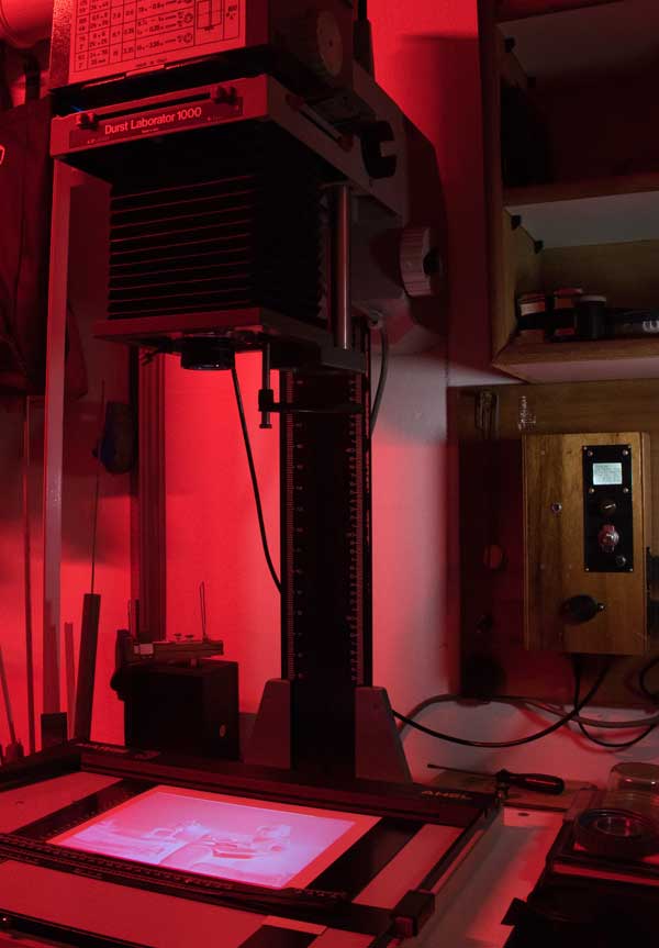
Starting point, a Durst Labotator 1000
I have a Durst Laborator 1000 with 135 mm up to 4 x 5″ negative carrier. It has only a condenser head. It uses a 150W incandescent bulb and condenser lenses that need to be changed according to the size of the negative, as shown in the picture below.
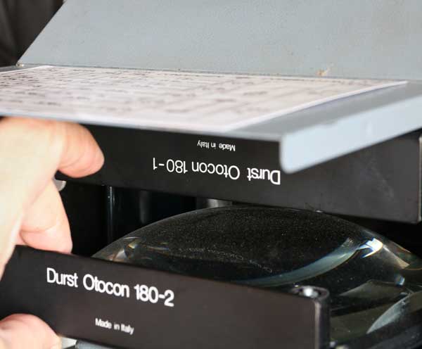
The basic idea was about adding to the enlarger the possibility of using a diffuser head with LEDs. The condenser lenses would be removed and, in their place, a box with LEDs in the “ceiling” and a diffuser screen on the “floor” would be installed in order to be able to switch between one system and another as desired.
Escolha dos Leds
Variable contrast photographic papers are sensitive to the range of the spectrum corresponding to blue and green light. The blue light causes an additive effect of the three emulsion layers and the density rises rapidly causing high contrast. The green light does not respond equally in all three layers and the density develops more slowly in response to a certain degree of exposure resulting in an image with more transients and less contrast. To see this in more detail follow this Ilford link.
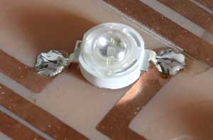
Based on this information I decided to make a grid of blue and green LEDs. I did an initial test with RGB led strips and the result was encouraging but I thought it lacked power. I also thought that the Led Strip itself is not very robust and in case I had to replace a defective LED that would be difficult. I then opted for 1-watt surface mounted diode (SMD) LED. Considering the size of the grid to cover 4 x 5 ” negatives the size of the LEDs themselves and their power, I found that 36 LEDs forming a 6 x 6 array would be enough.
36 W in LED light matches roughly 150 W of incandescent light source as I found on some websites showing that rough conversion. I chose Blue Royal with wavelengths 440-450 nm and Green with wavelengths 520-523 nm.
How to wire the LEDs
LED stands for Light Emitting Diode. These diodes have an ideal operating voltage in which they emit light at their best performance. Below this voltage they do not emit and behave like an open circuit, that is, there is no current, even with voltage applied at their terminals. Already in the operating voltage it behaves like a short circuit, that is, they do not offer any resistance to the current passing and that rises according to what the voltage source + circuit are able to provide. Therefore, just a little above the operating voltage LED may already burn easily because the current rises without anything to prevent that on the LED side. It just melts by producing heat. Therefore it is very important to control the current and don’t let it pass the limit that in the data sheet of the LED appears as Forward Current:
Example of a datasheet:
Color:Royal Blue
WaveLength/Temp:440-450nm
Foward Voltage(V) :3.2-3.4v
Foward Current(mA) :350mA
For the voltage in the LED circuit I chose to work with a 12V supply as this is a standard market voltage and the sources are cheap and easy to find. I bought a 10A but a 5A would be enough as I calculated it later.
As each LED has a Forward Current from 3.2 to 3.4, for a source of 12V the default solution was to connect 3 LEDs in series giving a drop of about 10V.
Now, the question of controlling the current: The most common way of doing this is to put a resistor in series as well. But more effective is to put a transistor on top of a resistor. I used an LM317 with a resistor of 3.9 Ohms. Since the LM317 always gives a voltage drop of 1.25 V (this is a constant of its own), using this resistor it works like a faucet in the circuit that only lets 1.25 / 3.9 = 320 mA to pass, protecting this way the LEDs that have 350mA as Forward Current.
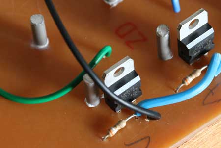
Above you see the LM317 (they are black at the base and with a hole at the top) and the resistor (a little cylinder), soldered on the board at the opposite side of the LEDs. Aluminum pins are heatsinks that I improvised as a precaution. It is said that these LEDs produce a lot of heat and then I drilled the board right where they are and put those aluminum pins with a white paste that is good for improving the thermal contact.
The basic concepts of these circuits are discussed in a very didactic way in the following tutorials: AddOhms, to understand why LEDs need current limiters. Lewis Loflin, to see a circuit assembled with the LM317 transistor.
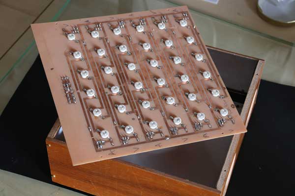
Taking this decision on the key figures I was left with a circuit of 36 LEDs being 18 blue and 18 green. They would have to be mounted on an 18 x 18 cm plate to be able to enter the gap left by the condenser lenses of the enlarger.
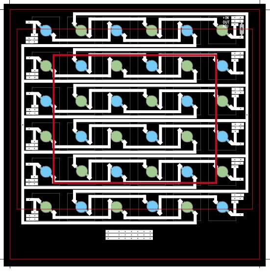
This is the final design of the board and position of the components. The smaller red frame in the center (thick border) corresponds to the position of the negative 4 x 5 “.The next red frame, with a thinner border, is the limit of the white screen. The LEDs are in their colors and in the corners it can be seen the location for the resistor and transistor (three holes) as marked in the upper right corner (in, out, and adj). In white we have the PCB (printed circuit board) tracks.
There were therefore 36 LEDs, 12 LM317 transistors and 12 3.9 Ohms resistors (called 3R9 on the market, perhaps for fear of decimals).
To engrave the printed circuit I used the Dry Film method. It is necessary to have a negative and mirrored film made with the drawing. Then you apply Dry Film to the plate (I used the method with water and it worked very well). Then you corrode the copper that needs to go away and stay with the tracks ready to receive the components. There are many Youtube tutorials about this. Search for “homemade printed circuit boards”. You can also find a supplier who makes the board for you according to your design.
[mks_col]
[mks_one_half]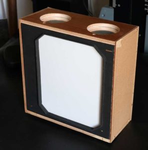 [/mks_one_half]
[mks_one_half]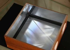 [/mks_one_half]
[/mks_col]
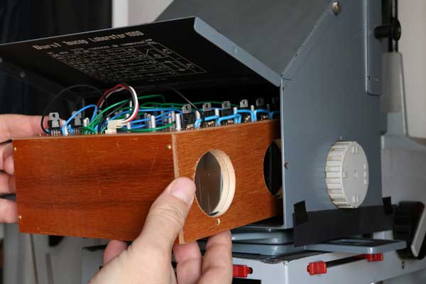
The box itself is very simple. This was made with 6mm plywood on the sides, 4mm on the front and 2mm cardboard on the back, to save space. Inside I covered with very thin aluminum plate to increase the reflection. The large round holes on the side were intended to improve the thermal conductivity and prevent overheating. As a diffusing screen I used a piece of milky plastic that I found in the trash of a electronics store and that was part of a flat screen television. I think any large camera GG would work as well. But I pondered that the TV manufacturer must have thought of optimizing the transmission of light while maintaining the diffuser aspect of the thing and that was exactly what I needed. It worked super good.
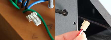
It was necessary to drill the side of the enlarger to pass the cable that feeds the LEDs. A soldered connector on the top of the board makes it easy to plug and unplug if needed. It is a cable with only 3 wires, a positive that is common and comes straight from the 12V source and two other negatives that regulate the power of the blue and green LEDs independently as will be seen below. On the total current, from what was seen above one can calculate by counting that 12 circuits with 320 mA each pull a total of 3.84 A.
How to control LEDs power output
Although a normal enlarger does not change the brightness of the lamp (except in color heads), with the LEDs, the variable contrast must be obtained in different proportions of blue and green. In this way it was necessary to think something able to control the power independently in the two circuits: blue and green.
This was achieved by placing another transistor between the 12 V source and the LED board. It was a TIP120 transistor. What’s interesting about it is that when you apply a voltage between two of its pins it acts like an open circuit, there is no current flow between the two. However, if you apply a voltage to a third pin, this fact has the effect of opening the faucet and a large amount of current can flow through the first two pins. It functions as a switch for a powerful circuit driven by a weak circuit.
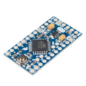
A micro-controller is then used, I used a 3.3 V Arduino Pro-Mini which can, according to an a program you create, apply voltage to the third pin. We say that this is a logic voltage, it is like a command and not a voltage to perform some work, it is low, 3.3 V in this case, and it is only to “activate” the TIP120 so that it opens the current flow to the circuit driving the LEDs.
Although it seems complicated, our only contact with the Pro-Mini is to plug some wires into the holes it has at its edges. You need to learn what they are and not worry about what is going on inside the controller. There are two major advantages of the micro-controller:
- The logic voltage that it applies to the TIP120 can be of the PWM type (Pulse Width Modulation), this is what allows to vary the light intensity of the LEDs. But it is not in the sense of making the TIP120 apply less than 12V in the LED circuit, that would not work. What happens is that it applies these 12V (which it receives from the main source) intermittently, pulsating, with a “variable pulse width”. When we want the maximum power we have 12V constant, if we want medium power we have half the time 12V and half with zero V. It turns on an off at a very high frequency and it is not realized that the LEDs are actually blinking. This blinking does not affect the life of the LM317 which simply blinks together because its response time is more than enough to do so.
- With the micro-controller you can write a program that will turn on and off the enlarger, safety light, combinations of both, controlling the times and other functions that will be required to automate the process.Then, on the side of the micro-controller, what is needed is to allow the user of the enlarger to tell how much time the enlarger will be on, how much blue, green, with or without safety light and some other desirable parameters for darkroom routine. This is done by connecting logic pins of the micro-controller to the TIP120 and writing a code that uses the DigitalWrite command (written in the program) addressed to the pins assigned to the LEDs. A DigitalWrite (9,0) turns off pin 9. DigitalWrite (9,255) turns pin 9 on the maximum that is 255 (8 bits). The program itself, you write on your computer, in an interface called IDE, and transmit it to the micro-controller via USB. There are many tutorials on the Web that teach to program micro-controllers of the Arduino family. An interesting one that talks about LED Strips, but that also applies to the circuit discussed here is this Instructables. If you are totally new to micro-controller a visit to the official Arduino website is a must.
The timer and user interface
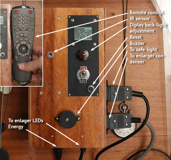
Well, you should have noticed that besides the box that goes inside the enlarger, you need another box that will control the time, power and colors that will be needed to print the photograph. This box is the timer that is usually used in the laboratory. A timer with some sophistication. It must have:
- A display where the exposure parameters are displayed. I used a Nokia 5110 LCD that equipped old cell phones and now sells a lot for robotics projects. It is good for darkroom work because it has back-light but can also be totally off (different from today’s cell phones that always leak light when turned on)
- A means to change these parameters. In the case I adapted an old DVD player remote control to communicate with the micro-controller.
- An IR receiver to read what is received from the remote control
- A relay to turn the safety light on and off and also the magnifier when in the condenser mode (when removing the box with the LEDs)
- A 12V power supply with at least 5A to power everyone. It can be internal or external to this box.
- A buzzer to beep you about what is happening
Based on my practice and wishes enlarging my own photos I thought something with the following functions that can be seen in the timer control screen:
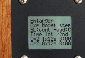
The two end lines contain the key exposure parameters. It is possible to do two independent exposures.
- C = 2 means contrast level. Zero only turns on green LEDs (minimum contrast), 6 only lights blue LEDs (maximum contrast) and intermediates make proportions between the two.
- 1x12s means that you can program repeated equal exposures (up to 9). 1x12s means that there will be only one 12s exposure. There is an interval of 2 seconds between these exposures and a beep. This is good for making test strips or for dodging / burning specific areas of the image according to a set time.
- B: 00 is where you can place a base exposure of up to 99 seconds. From there enters the sequence of repetitions programmed in the previous item.
- SL stands for Safe Light. There are two modes, cont and auto. In cont the darkroom safelight is on all the time, continuous. In auto, it switches off automatically whenever the enlarger is turned on.
- Mode is the exposure mode. Step means that there will be an interval of 2 seconds between the scheduled exposures. Once, means that both base “B” and the programmed steps will be executed all at once without interruption. Interesting when you’ve come to a conclusion about exposure after performing some tests with steps.
- Head: it is only to switch between “C” condenser, and “D” diffuser, incandescent or LEDs.
- One function that does not appear on the screen is Focus. It is a button on the remote control that turns off the safety light and lights up the enlarger at full power for focusing. One point that is a little strange, using LEDs, is that blue produces a very dark and barely visible image. Green is much better, but the color that is projected seems something lunar, different from the familiar image produced by incandescent light. Maybe if I make another head like this, I’ll consider adding red LEDs just to help with that view.
This part about the interface was just to give you ideas of what it is possible to control and do with the Arduino platform. It is much better and more flexible than a traditional timer. But I think everyone will imagine something that suits their work routine better. The routine to be recorded on the Arduino will, in any case, be just a combination of turning on or off digital ports and introducing a delay between one thing and another. Maybe someone prefers a matrix keyboard instead of the remote that needs IR receiver, interpret codes, etc, etc.
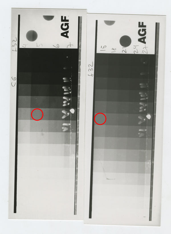
Results
To test I have printed an AGFA scale with various gradations of gray. The magnification was 2: 1, i.e., the negative of 10 x 12 cm would correspond to 20 x 24 cm in the print. The result shows that to obtain an average gray, zone V, it took 5 seconds with maximum contrast (only blue, left strip) and 15 seconds in minimal contrast (only green strip, on the right). But the most surprising is that the lens, a Schneider 150mm Comparon, was in f/32, a very small aperture that I could never try with the incandescent lamp. I consider these times too short for normal work and should introduce an adjustable power reduction factor into a new version of the software. But anyway, it’s better to be over than to be lacking.
For those who do not know an enlarger
After writing most of this article I realized that a lot of people today interested in analog photography may not yet have seen an enlarger. Then I recorded a video that demonstrates this LED head and also shows how a B & W printing is performed in a traditional analog laboratory.
Conclusion
I think I will hardly use the condenser again. I also tested 135 mm film negatives and despite the smaller area of illumination and consequent larger magnification, the times and apertures were very good compared to the use of condenser. It was something like 15 s in f22 for a negative with normal density.
A highlight of this new system is the ease of exposing different areas of the picture with different degrees of contrast. For those who use a color head this may be easier but in the case of black and white enlargers, with the need to changing filters and risk of losing registry, we usually avoid this type of situation. But with the LEDs this really gets very easy.
As I said at the beginning this is not a tutorial like a recipe to follow blindly. But I hope it will serve as an incentive and facilitator for others to venture to create using the information contained herein. One possibility that I find quite feasible for those who are entering analog photography and have a hard time finding a good enlarger would be to make a box of LEDs like that to fit in the back of a large format camera and use it as an enlarger. The apparatus is lightweight, small and costs very little. I also tested the question of temperature and in fact it does not heat almost anything in normal operation. After something like 1 minute focusing on an image (maximum power) the temperature inside the box reaches about 35 ° C and the on and off of the enlarger, in normal routine, is enough to ensure that it stabilizes between this and room temperature.
The total cost of the project was around 80 USD, buying LEDs direct from China, engraving the circuit board at home and making the boxes with scraps of wood. I’m not counting the remote that was from an old DVD. All software is free. What really costs is time to research, learn and build it all. But this one, I hope I have shortened a lot for you.
About sharing code or a more detailed project
I received many requests for sharing the Arduino code and complete project specifications. There are two possibilities:
- If you are not familiar with the knowledge involved in such a project, please believe me that there is no way to make instructions detailed enough to allow one in blindly following it up and get a satisfactory outcome. I would certainly, naively, forget to mention something that looks evident to me but would not be so for you. Too many chances to frustrate your expectations and too much responsibility for me in driving you to a complete failure.
- If you are familiar with the knowledge involved in this project, you certainly realised that this tutorial, plus the video, are plenty of information and insights for you to tailor your own solution. The key and tricky parts of electronics are covered and will save you a lot of time. The user interface is fully shown and you know it will be much easier to write your own code than understand mine (that is mixed up with other routines and was not written with code legibility standards).
This is intended for photographers. If ou are a photographer belonging to the first group, not electronics/computing savvy, the best way to go about it is to show this material to one of your acquaintances who can handle it. If you are a photographer belonging to the second group, having some of the necessary skills and enthusiastic to study more and fill possible gaps, go ahead, your project will certainly be an improved version of mine.
Great article, I also have a Durst Laborator 1000
And I was considering using the intrepid led enlarger set up which is designed to fit a 4×5 camera Graflok back.
https://intrepidcamera.co.uk/products/intrepid-4×5-enlarger-kit
I have this setup with an Intrepid mk 4 camera at the moment, but the Durst would provide a more sensible set up.
Regards
Andrew
Olá amigo, bem, estou ansioso pelo seu artigo publicado na Web para ver como fazê-lo. Fiz cálculos para trabalhar com 24 volts e poder conectar até 6 LEDs em série, mas, em qualquer caso, são necessários muitos drivers de potência pwm e são bastante volumosos. Eu tenho uma área para o magnifax 3 que não pode ser maior que 120 x 120 mm e, portanto, 36 LEDs + drivers me forçam a trabalhar em vários andares. Minha idéia era ter linhas separadas de verde e azul para a área marginal central e, portanto, tudo fica complicado. Sem mencionar o calor !!! Obrigado por compartilhar.
Olá Wagner,
quero agradecer a sua resposta rápida e gentil. Seu projeto me fez querer experimentar e, embora tenha certeza de esperar até março pelo seu livro, começo a testar e a tomar medidas. Não tenho muitos problemas com o software porque sou programador e conheço vários idiomas, incluindo o Arduino. Usar LEDs RGB me parece uma boa idéia para ter uma melhor distribuição das fontes de luz (2 cores no local físico de 1 LED) e também para ter luz branca para operações de foco, margem, etc. Eu me preocupei um pouco mais com a questão dos valores de contraste. Vou procurar as curvas do filtro Ilford para encontrar e programar uma relação entre% e escala de valor de contraste 0-5 / 6. Se eu o encontrar, compartilho com você. No momento eu não te incomodo mais 😉 Estamos em contato e mal posso esperar para comprar seu livro, porque a experiência que você tem é enorme. Voce fala espanhol?
Até logo!
Guillermo
Guillermo, eu não vou publicar um livro. Vou colocar tudo aqui no site mesmo. Hoje gravei a PCB Printed Circuit Board dos LEDs, está indo rápido. Até março eu publico. Sobre línguas, leio um pouco mas não falo ou escrevo em espanhol. Consigo me comunicar bem em inglês, escrito ou falado, e leio bem francês (falar é mais difícil), além, é claro, da língua mãe português.
Excelente artigo que me fez querer modificar meu antigo Magnifax 3! Eu só mantenho pocas preguntas, se não for um incômodo para você.
1) No Magnifax 3, o tamanho máximo é 6×9. Você acha que, com uma matriz de 16 ou 25 LEDs em vez de 36, poderia ser o suficiente para trabalhar no F11?
2) Com que método preciso é possível calcular os níveis intermediários de contraste? como combinar o brilho de cada cor para obter um contraste de 2 1/2, 3, 3 1/2 etc. etc. ?
Muito obrigado. Estou seguindo você no grupo Darkroom, também sou fã de eletrônicos e de dark room e estou escrevendo para você em português (Tnks Google) porque, este ano, espero poder me mudar da Itália para morar em Portugal
Olá Guillermo, grato pelas palavras gentis.
1) Creio que para um tamanho 6×9 cm, apenas 9 leds azuis e 9 verdes dariam a mesma potência luminosa que 36 para 9x12cm ou 4×5″. Como as fontes de 12V são muito fáceis de achar, aconselho também colocar como condição de seu projeto fazer circuitos com LEDs em números múltiplos de 3. Seriam então 3 circuitos por cor, com 3 leds cada um. No meu Durst eu fiz 6 circuitos de 3. Basta você fazer a metade.
2) Deve ser muito difícil fazer uma tabela de conversão dos filtros multigrade Kodak ou Ilford para proporções de LEDs azuis e verdes. Eu preferi fazer várias misturas indo de 100% com 0% e diminuindo de um lado, aumentando do outro, até chegar a 0% com 100%, de azul x verde. O fato é que você terá vários níveis de contraste, como que eles se relacionam com os padrões dos filtros multigrade, eu sinceramente não me preocupei em saber.
Aproveito para dizer que até o final de março vou publicar um tutorial realmente completo, com medidas, passo a passo, código Arduino, esquema de montagem e tudo que é preciso para se montar uma caixa tipo Graflarger Back. Ela será adaptável a qualquer câmera 4×5″/9x12cm, transformando-a temporariamente em um ampliador. Será com LEDs RGB de 3W. Há uma vantagem grande em se usar RGB pois o vermelho, embora não impressione o papel, é mais visível e ajuda muito na focalização, ou quando se faz dodging & burning. Será possível nesse projeto, já que a programação do Arduino estará aberta, se “dosar” azul x verde, de acordo com as preferências do operador, criando sua própria escala de contrastes em 10 níveis. Se vc não estiver com muita pressa aconselho esperar pois essa nova versão será muito mais interessante que a primeira. Abraços, Wagner
Fantastic, well done! Thank you.
Hello, thank you very much for sharing your experience, very good article. I want to make an enlarger head and with your text and others that I have read, I am thinking about the best possibility within my reach. I have no knowledge of electronics or programming, I am thinking to use real blue and green leds, and to adjust its intensity by means of an attenuator that I can send to do, and use a classic timer, that is, I would work with the same exposure time for green and blue. I think that by graduated the intensity in different percentages between green and blue, I should be able to correctly dose the contrast, what do you think about this possibility? I also plan to include red LEDs, although I do not think it’s through the attenuator to dont make it more expensive. All advice is welcome and the results of what I will get will be shared, of course.
Very well documented article, Thank you!
I had this same idea some years ago, but have no place where do it, since my actual place is too small for a real darkroom…
Moreover I had a problem of flooding the negative evenly: my concern was that LEDs could produce some areas of more light acros the negative surface.
That should depend from the distance between LEDs but also from the distance of LEDs from the diffusion glass below.
But also frome the quality of LEDs.
Could you please provide those measurements?
Could you also tell us which “brand” of LED are you using ?
Thank you, and many compliments for your way to build things !
Massimo
Sorry for my late answer. I added a caption on the picture with LEDs scheme with all the measurements. Please let me know if that is ok for you. Thanks for stopping by.
Great article, i like the way you are sharing your knowledge. I am working on a LED head project for years now. Making experiences with electronics and Arduino programming was more important to me than finishing a prototype. Honestly the programming part consumed the most time because i wanted to build a control unit with old school 7-segment LEDs, nobs and switches which fits to my old school enlargers.
Your article brought me back on track, i decided not to fiddle around any longer. I will finish my first light box soon and then i will see if it fulfills my expectations. Certainly i will not stop working on the next level, a real SplitGrade system like the Heiland (i decided to use a Raspberry Pi to control the Arduino), but i’ve understood that without printing pictures and making experiences with the LED head, the whole work does not make sense.
So thank you for your inspiration.
Hi, I’m a large format photographer and I also have been operating a public darkroom in Hanoi, Vietnam. We have a Devere 8×10 auto focus enlarger with color head but the electronic is incomplete. While we could be manually focus and rasing/lowering the head/base board, the color head system couldnt be used. I have been reading about multigrade led light source and it brought me to your article. However my electronic skill is next to zero, so may I ask is there any chance you could spend some time and skill to make a led light source for my enlarger? I’m willing to pay for all the materials and of course your time and effort. Please help this fellow larger format shooter out.
Looking forward to hearing from you.
Regards from Vietnam.
Great inspiration, thanks for sharing.
With friends, we are preparing also LED conversion for enlarger. And may I have one question, please?
Blue leds seem to be less bright than green (according some specs, for 1w blue is about 60lm and green 100 fo example).
You have 1:1 ratio which seems strange at first. Is paper more sensitive to blue?
Or..it really doesn’t matter?
If you have any clue for us, that would be great 🙂
That is a good point. Lumen is a unit modulated by human eye sensitivity and we are far more sensitive to green than blue. But paper behaves differently. I can tell you that in order to reach the same density on paper I need to expose 3 times more using only green LEDs than only blue LEDs in full power. Although visibility would lead me to think the other way around. When I first projected this head my major concern was about getting an evenly illuminated area no matter with blue or green color. The 50/50% grid was the normal solution. Today I would consider more green LEDs, although this can be well managed with time and/or power. A side effect of all of this, that you may like to consider, is about including some red LEDs on your head. That is because when only blue LEDs are at work the projected image is very dim, difficult to do burning and dodging. The red LEDs would do nothing to paper but would help a lot in visualising the image in case it has to be worked during exposure.
What a perfect idea and developement. Congratulation!
I think I have to follow this and do it at my own over next month.
Is there somewhere a link to the userinterface with Nokia display and the software I’ll need for the Arduino?
Would be much appreatiated.
Excellent article, thank you. I think there are quite a lot of people still interested in analogue photography, which puts me in a good mood, because in this way film will be still produced in the future. Your project is extremely good engineered. I built a 8×10 enlarger myself and I put also 18 pieces of 3W LEDs as a light source, but my light source is a lot simplier, because I am not as skilled as you are, but it works fine. Almost any enlarger head can be cheaply converted to LED.I also converted my Meopta Magnifax 3a , I used 12 pieces of 3w LED chips. This enlarger heats up very much with an incadescent bulb, so LEDs are very appropriate for the film negative, which remains cool and glassless negative holder printing is safer.Perhaps I am going to convert also my Durst 4×5 enlarger, but I still like the condensor effect in the prints, especially in low density negatives.
best regards, C.
I recently discovered LEDs, sensors and micro-controllers. It is really funny to work in homemade projects using them: cheap and very effective. I am glad you liked the article and wish you a lot of fun in your projects too.
I also made a red safelight with 10 deep red 3w led chips and I had to dim them strongly ,however I could also put the light further away with no dimming. I have never expirienced so bright darkroom , it is really awesome. The light was tested for 30 minutes with no sign of fogging the paper. So no more tripping in darkness. I also ordered an Arduino microprocessor to drive a stepping Nema 17 electromotor for making a base roller for my Jobo drums, but also have to learn how to programme it and hoping to find a video tutorial for the project. I wish you successful work in the darkroom too.