Magnetic Stirrer
This is a tutorial for you to build a magnetic mixer using a fan as the motor. With it you will have ease, efficiency and quality to mix the solutions used in analog photography, such as developers and fixers.
It produces a vortex in a container with water. The reagents, usually in the dry form of powder or crystals, are added slowly and dissolving according to their solubility characteristics. The magnetic mixer is an alternative to stirring the solution with a glass stick, which is very tedious and not very productive.
Watch the video to see how it works and then find more detailed specifications and explanations about the assembly here.
Energy
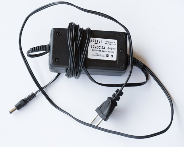
You will need a 12V power supply that can be like the one above or those that the box is already a plug, like those of cell phone chargers. At old and used fairs or electronic scrap shops they are easily found and cost very little. In addition to 12V they are specified by the current, measured in Amperes or Milli-Amperes, symbolized by A or mA. As the consumption of the mixer is very low, you will hardly find any source with a smaller capacity than necessary. Therefore, being 12V and being above 600 mA or 1A, it will do. I think the ideal would be 1A, as this will give you the flexibility to use it also in some other project.
Motor
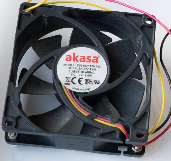
The ideal motor would be one of these coolers, a fan used to cool circuits and CPUs. Buy a 12V. The power is normally expressed in Watts, symbol W. In this photo we have 2.4 W. Sometimes the current comes in mA. With 2.4 W the current is 200 mA (just divide 2.4 by 12). But don’t worry about it too much. Being 12V and having this size that is 8 cm on the side, it will certainly work with the 12 V power supply.
Conector
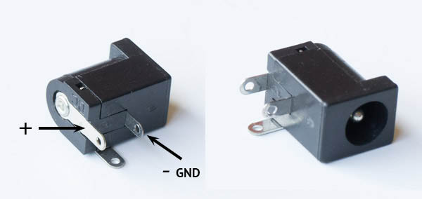
It is interesting that you can connect and disconnect the mixer from power supply. For that purpose, include a connector like the one in the photo, but one that is compatible with the pin of your power supply. This connector will be attached to the mixer panel.
Magnets
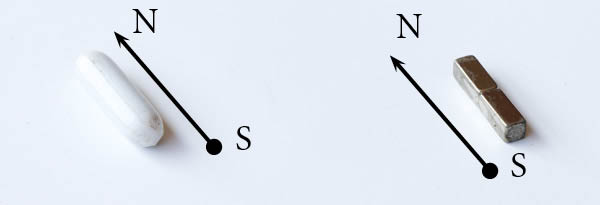
You will need a special magnet for the stirrer. That’s what goes into the solution. It’s the one on the left in the photo above. It is a magnetic material wrapped in a teflon cover. Usually physical stores or online selling material for laboratory offer this type of accessory and even have a few different models. It is called “magnetic bar” and also “ballerina”.
The other necessary magnet is the one that goes over the motor. In this case it can be a generic magnet, provided it is a “power magnet”, a neodymium magnet. The intensity of the magnetic field will be very important for the performance of your stirrer. If it is weak it will not move the ballerina magnet that will be inside the solution. Do an online search for “neodymium magnet” and see some of compatible dimensions to be attached to the cooler. Anything 20 to 30 mm long and with a 3×3 or 4×4 mm section will do.
Attention to the orientation of the magnet. They have North and South, as shown in the photo above, along the longest dimension of the magnets. It is necessary that when the magnet is in the beaker, lying down, that it will align itself with what is glued to the cooler. If you buy an excellent neodymium magnet but in the shape of a disk, for example, it is likely that its axis is oriented in the direction of the disk axis. It will be perpendicular to the ballerina’s orientation and it will not work.
It is possible to amend two or three magnets. I did that in this mixer. In the video I had only put two but then I thought it would be better to put three to increase the strength of the field. When two magnets naturally seam in the longitudinal direction it is a sign that their orientation is longitudinal too.
To buy, do an online search for a neodymium magnet and you will see that hundreds of options soon appear .
Voltage regulator
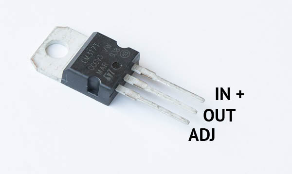
This LM317 regulator has 3 “legs” and therefore there is a risk that it will be inverted. Attention to the correct position. The names of these terminals are Vin +, which is where the positive voltage of greatest value comes in. OUT is the voltage already lowered and ADJ is adjust, where you tell the regulator what voltage you actually want. This is the terminal where two resistors will be coupled, one fixed and the other variable. Placed with the written part facing up, these three pins are in the position as shown in the photo above. To buy just search for the same name: LM317 and check that it has this presentation / format.
Fixed value resistor
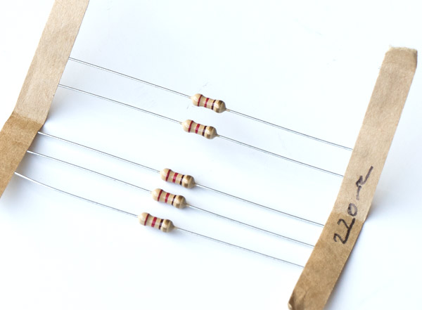
This is what the fixed resistor looks like. They are usually sold in packages of at least a dozen. If you buy online probably the minimum will be 100 units. The individual value is usually cents. It has no polarity and either side works the same way. The value used in this project was is 220 Ohms. That’s all you need to specify for your purchase and make sure it looks like the ones in the photo above.
Variable resistor, potentiometer
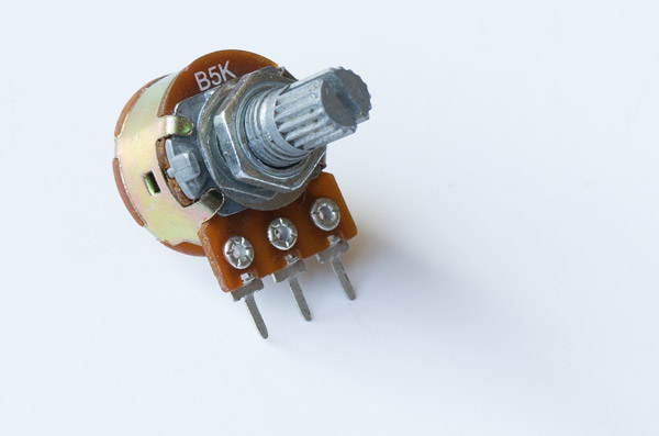
This is the pot. In the project I used a 1K Ohm, although the one in the photo is a 5K. But here is just to take a look at its appearance in close-up. The middle pin must always be connected. Then you can choose between the one on the right or the left for this project. The difference is whether the speed will increase by turning the axis clockwise or counterclockwise, but it will work anyway. To get a professional look, buy also a graduated button like the one I installed.
To buy search for 1 K Ohm pontentiometer. There are also sliding models but these are more difficult to install as they need a slot cut in the panel.
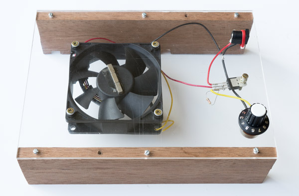
Physical assembly
It is all very simple, there are just a few points to which I want to call your attention.
- The first is that it will be necessary to place four spacers to give a sufficient but not excessive height for the magnets to rotate freely. In the photo above you can see that I put a piece of a black hose and the magnets are very close to the acrylic panel. Proximity is important so that the magnetic field does not lose intensity in the region of the ballerina magnet. The screws, with conical head, can be of M3 (1/8″) size and with nuts. Alternatively, some nuts can be used as spacers.
- Do not close the space between the fan and the panel. The wind needs to circulate, otherwise it will force the motor and overheat.
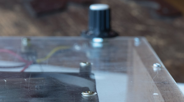
- It is good to think of embedding the head of the screws in the panel so that it is a flatter and better base to support the container with the solution. In the video this is shown with the use of a fine drill to mark, a thick drill to make the recess where the conical head of the screw will enter, and finally a fine drill to finish pouring the hole. Drilling the entire hole first and trying to enlarge it later, “just a little”, brings in a great risk that the thicker bit will cross the entire thickness of the panel.
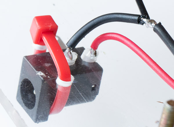
- The four holes that appear in the drilling scheme to receive the power connector are for fixing as shown in the photo above. Two are for wires and two for a nylon clamp.
Electric circuit
The circuit is so simple that once the components are positioned it is very easy to make connections with solder. The welding process, as you can see in the video, is very simple, a little solder is placed on each element, then the elements to be welded are joined together, the iron tip touches the joint and immediately the welds melt and join the parts while they are held in position.
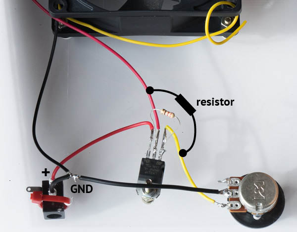
Check that the LM317 has the written part facing you when the mixer is upside down as shown in the photo above. The assembly sequence can be in this order:
- Connect one side of the potentiometer directly to the ADM tip of the LM317 (yellow wire).
- Connect the + pole of the power connector directly to the IN of the LM317 (red wire).
- Connect the GND pole of the power connector to the center end of the pot, but leave a bare segment to make a splice.
- Connect the black wire (GND) of the cooler to the black wire that connects the potentiometer to the 12V GND.
- Connect the red wire (+) of the cooler to the OUT (center) pin of the LM317.
- Finally solder the 220 Ohm resistor by connecting the LM317’s ADJ and OUT tips.
I soldered directly on the two ends of the LM317 itself. An alternative would be to open two points on the red and yellow wire and place the resistor as it is drawn in black on the photo above.
Some coolers have a third wire, yellow in this case, but it is not used and is left loose.
This is the link to the holes template: holes template.
Before you turn it on, go through points 1 to 6 above again, check if everything is connected in this way. Do not leave the source connected to the mixer when it is not in use, because even with the engine stopped, current will still flow (useless) through the LM317. If you prefer, place a switch.
Now just turn it on and mix it all !!
Nice article! One thing to think about it the cost of building something like this vs buying a used lab stirring hotplate. A lot of used lab gear can be found online these days. And stir plates are a common lab item. I’d suggest people look for stir plates that have built-in heating. It’s super convenient to have a stirring hotplate as they can help with the dissolution of chemicals. Keep in mind, there are hot plates that don’t stir, and they look very similar to ones that do, so do a little research on any item you’re thinking about buying.