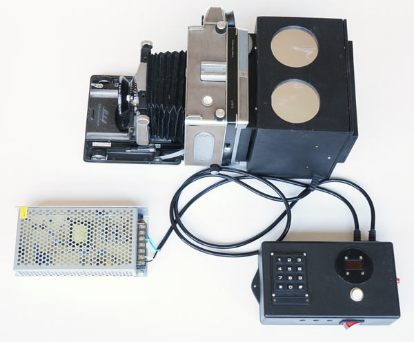
This is a relatively complex project but the end result is so rewarding that it is certainly worth the effort. The objective is to mount a diffusion enlarger head for negatives up to ¼ plate, that is 4 x 5 “or 9 x 12 cm. In this tutorial this head is designed to fit into a large format camera that accepts standard film holders and have a Graflok Back. This is a type of back in which the ground glass can easily be removed to put some other accessory in its place. Usually an adapter for 120 films is the case. But the diffuser box is the most flexible part of the project and its design can be adapted so that it can be accommodated into a variety of existing enlargers, even in smaller formats.
The design also includes a special timer to control this LED head and produce variable contrast when using multigrade papers. The timer also has two 110 / 220V outputs to control darkroom safelights and a conventional enlarger.
The advantage of using a camera is that enlargers of this size are becoming difficult to find; while if you are thinking about making an enlarger for this format you probably already have a camera. If not, many of these cameras, of good brands, have been offered at very reasonable prices. I often hear of donations (but only when piece is gone). Of course, you can think of a complete magnifier project, but the camera already has a focus system with rails, bellows, lens board and fixation method that are difficult to reproduce in a homemade project.
My first project of this type was for a Durst Laborator 1000. The big news in this second version is that I am using RGB LEDs instead of just blue and green. This makes it much easier to use it because having the red available, although it is not “seen” by the photographic paper, it helps the operator to visualize the projected image. I decided for this change because when using the magnifier with only green and blue, I noticed that when the print asks for maximum contrast and only blue LEDs are activated, the image is practically invisible. First because it is common to use apertures such as f/16, /22 or even /32, which already makes the image very weak, and second because our eyes are very little sensitive to blue. This makes dodging/burning very difficult. But in this new version the red is activated every time the head is lit and we always have a very clear and easy to work image.
Table of contents
Diffuser box – LED head: Construção da caixa que irá conter a placa com os LEDs, o difusor e o encaixe para o Graflok Back
Leds board I, gravação da placa de circuito impresso
Documentation: access to apenasimagens_led_rgb_V1_english.zip containing the sketch, pcb drawing and other information
If there is any greater difficulty with some of these parts of the project I suggest to outsource by ordering it from someone who works in the area of woodworks, 3D printing, electronics or microprocessors. I personally have no interest in making these heads whole or in parts. My contribution to analog photography and its brave photographers is limited to the publication of this project with all the details I could consider. I take this opportunity to say that everything described here was actually produced, tested and works exactly as described. This is the limit of my commitment: that everything written in this tutorial is true. I don’t want to scare anyone, but having some experience with projects with microprocessors, I know that sometimes a power supply, a solder, a component, a poorly implemented adaptation put it all down and consume hours and hours of testing and debugging even if you find and correct the error. Most of the components, as far as I know, are international and can be found on known generalists websites and others specialized in one or another area. In electronic components I believe that a budget of around US$ 100 will cover it all. But this estimate does not take into account freight charges when shopping online.
Finally, I make it clear that this project is of my own development and I share it as freeware for any use, including commercial, in case someone wants to manufacture and sell the project in part or in whole.
As I have the habit of clicking on the “donate” button on sites that help me without charging anything, usually encyclopedias, libraries, tutorials and manuals, sites that I usually visit, here is my “donate” button if you are also adept at showing recognition in these situations. Your donation will be a great incentive for me to continue publishing useful content for the practice of analog photography.
Difuser box – LED Head
I will make the tutorial very detailed thinking about someone who has no practice in the areas it involves. I will give some tips that are very basic for someone who has more experience. I beg for the understanding and patience of the experts.
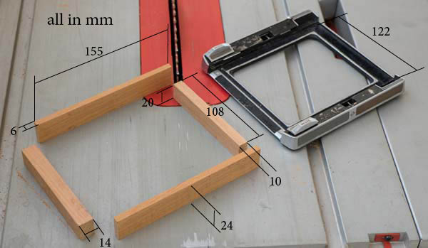
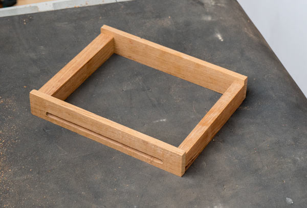
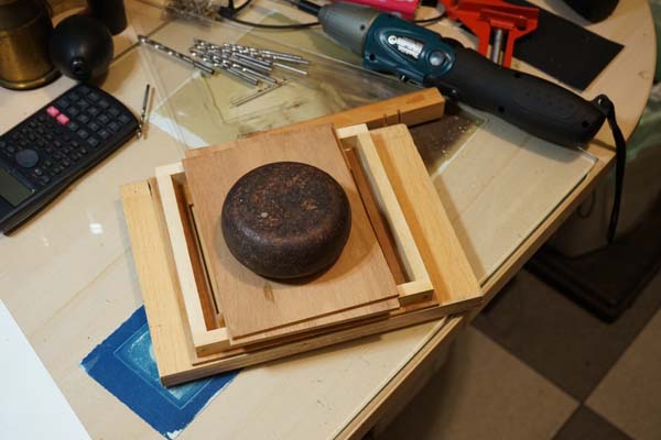
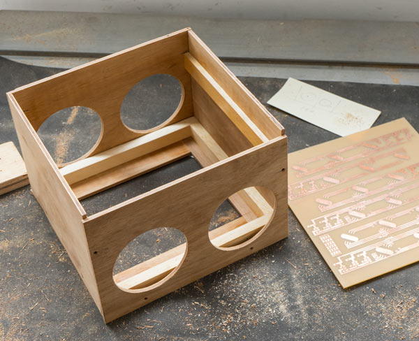
It all starts with 4 pieces of wood. Use solid wood and preferably recycled from old furniture as they are usually stable, harder and better to cut than wood that is coming onto the market now. I believe that using a table saw to obtain flat and square cuts is essential. If you do not have one, it is better to look for a cabinetmaker. The pieces are so small that he won’t charge that much.
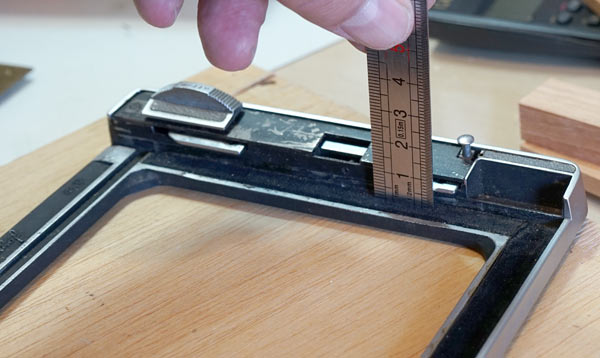
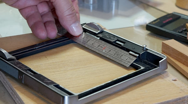
These four pieces will fit in the Graflok Back frame. The central span will be slightly larger than the span of the camera itself. But this can vary from one model to another. At Linhof it was about 5 and 3 mm larger at each edge, as shown in the picture above. Another point to note is that the height of the shortest pieces is 4 mm less than that of the longest. This is to create a gap through which the negative carrier will enter. This piece will go in and out on the back of the camera and so it cannot be very tight. Eventual light leaks in an enlarger are not as serious as in photographic cameras.
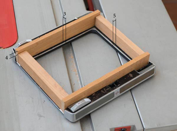
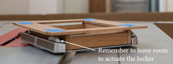
The box itself will come over these 4 initial pieces. The photo above shows its base laid on the frame and mounted with blue adhesive tape. It needs to be larger to accommodate the LED board. The height of the initial frame should be as small as possible, but it must be possible to actuate the latch that attaches the box to the camera back. In the case of this Linhof, it was necessary to leave 15 mm so that the latch can be slid. Therefore, the height of the sides of this first frame was 24 mm.
Before fixing the frame you need to think about the claws that will hold the box on the back. The height of the claws is usually 5 mm, but it is better to confirm and also check the thickness and depth it reaches in the case of your back.
Also check what extent the claws take when entering to secure the frame. Once these conditions are verified, you can prepare the fixing slot for your box.
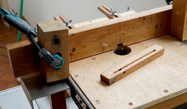
I tried to do the project using the least specialized tools. But this groove is much better if done with a router, as shown above. I made a test with a scrap piece of wood to see if the fit would be good and, once the height was confirmed, the final piece was passed through the router. The result is the photo below.
An idea would also be to make the groove on the whole lateral length with the saw. But this could weaken the piece because the groove is deep (check how far your camera’s claw enters the piece). In any case, if after making that cut from end to end, those are filled with the same wood, very tight and pressed with glue, you can thus restore its firmness and dispense with the use of a router.
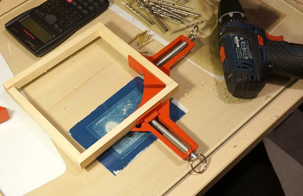
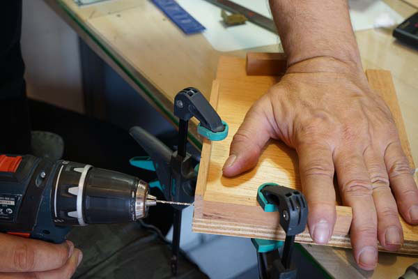
Now it’s the assembling. If you use only one screw, also use wood glue. Better a flat-head screw instead of a pan head as it must leave a smooth surface. Do not try to pierce the parts by holding them with your hands only. If you don’t have 90º clamps like the one in the photo below:
Use a very flat wooden board and secure the pieces with common clamps as in the photo below. Drill the thinnest hole into which the thread should catch and then loosen the back piece and drill the largest hole where the thread should run.
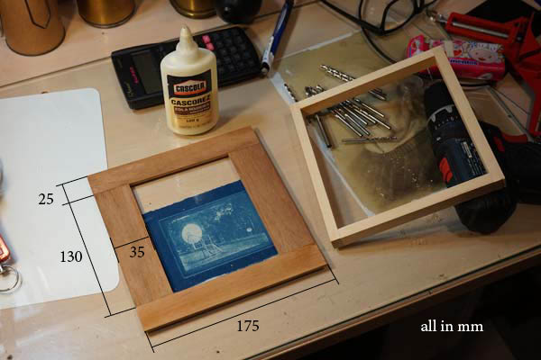
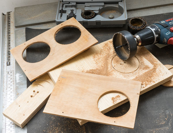
Then, the assembly of the box that will go over the frame. For this, it is necessary to start with the cutting of 4 pieces of plywood 4 or 5 mm as seen on the left side in the photo below. The best woods for this are the bottom of old drawers. Over it will come another wooden frame, built like the previous one but leaving a 4 or 5 mm border at the base (depending on the plywood you are using). The walls of the box will rise over this edge.
The external dimensions of this base are 180 x 175 mm. The internal measurements result in 130 x 100 mm, that is, the same 130 mm first frame, but narrower at 100 mm because the frame left 108 mm (see above). The reason for this narrowing along the side of the negative holder is precisely to form a frieze to hold it in position. On the right, in the photo above, is another frame that needs to be made and that will firm this base and serve as support for the walls of the box. Its thickness is not very critical. Use the slats that are within your reach. Anything from 10 to 15 mm will probably do. The external measurements must be 180 x 175 mm minus the thickness of the walls that you will be raising next.
Essa base da caixa pode ser inicialmente apenas colada e deixada de um dia para o outro para secar completamente. É preciso colocá-la sobre uma base bem plana (foto acima), ajustar bem o posicionamento enquanto a cola estiver permitindo movimentos e colocar um peso em cima para que a cola penetre nas fibras da madeira.
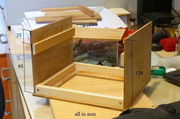
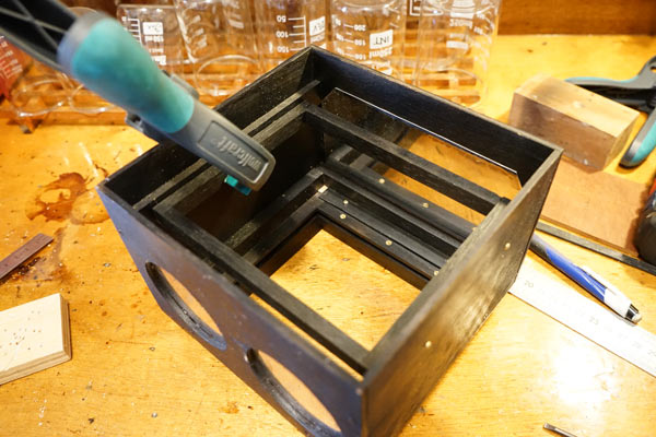
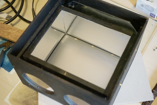
After drying the base, you must place two walls as shown in the photo. Before fixing them with screws, it is important to place two crossbars that will be supports for the LED PCB. Do not glue the walls as there is no need and so you will have greater flexibility in case you need to disassemble.
A big question here is about the 95 mm shown in the photo above. This is the distance the board with the LEDs will be from the diffuser. If it is too short, there is a risk that the diffuser will be illuminated irregularly. If it is too long the box can start to become unnecessarily clumsy and even impossible if you are making a box to go into a pre-existing enlarger. You have to experiment and it will depend a lot on the diffuser used. I believe that anything over 60 mm is already operational if you find a good diffuser material. As in this project, the space behind the camera was more or less free, I opted for these 95 mm as a very safe measure.
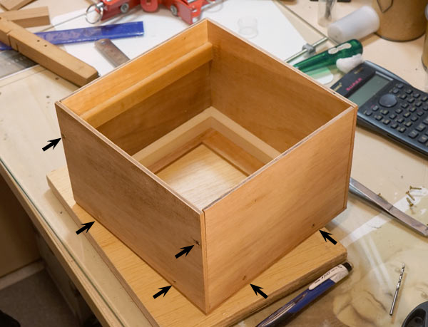
Once the exact measurements are verified, the other two walls can be cut and also mounted with screws only. Note their position indicated by arrows in the photo above.
I thought it was a good idea to open two large holes in these two walls that will then be covered with thin (but sufficiently rigid) sheets of aluminum. The goal is to facilitate heat dissipation. Below, when I talk about setting the power of LEDs at the time of focusing, I comment more on heat and temperatures. But the hypothesis adopted was to make the box without forced ventilation and almost closed to prevent the entry of dust that will certainly accumulate on the diffuser.
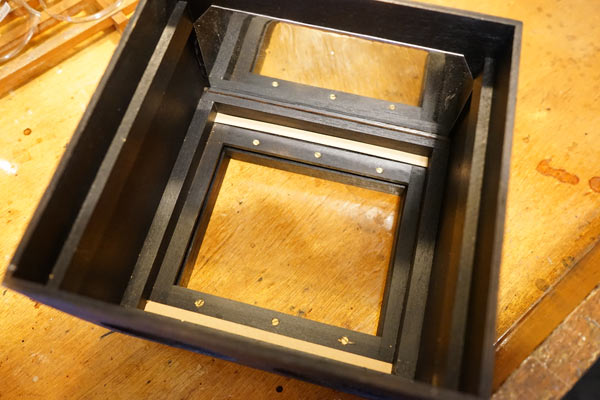
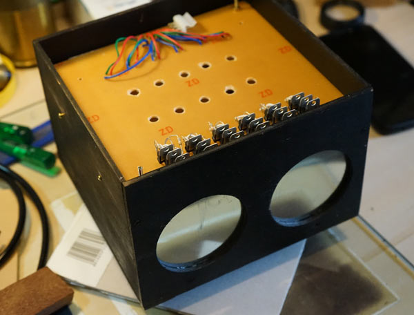
This is what the assembled box looks like. The PCB, which already appears on the side (although it is not that of this project) fits like a lid on it, supported on the sides and leaving a space for the components. A second lid will also come to seal the light. At the base opening the diffuser will be accommodated. This set will be screwed into the first frame that attaches to the back of the camera. The negative carrier will slide between the two.
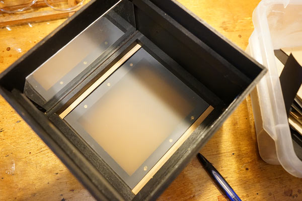
At that point the box was painted and aluminum foils were placed to plug the side holes. The 6 screws that are seen at the bottom are holding the base frame. The two wood sticks were placed to give a height and accommodate the diffuser between them. The diffuser could finally be fixed with some adhesive tape used in electrical and that can withstand a slight heating without drying or loosening. Ordinary electrical tape serves this purpose well.
This is not the final diffuser as it did not work well. It’s very translucent. A good source of diffusers is found in scraps of flat-screen TVs. There are several layers and the best are those that are very white, dull and through which we do not see any image, not even the outline of lamps and light sources. They are very thin, less than 1 mm. The choice of diffuser material is important because it must be diffuser enough to form a very uniform bright surface, when back lit, and transmitter enough to let in a lot of light pass through. But I don’t know how to specify that. I tried several materials till I found one.
The box has a much larger base area than the diffuser window. I was afraid that it would darken the edges. For this reason I decided to make a reflector tube closer to diffuser edges. It would be a kind of false wall. For this I set up another frame, as you can see in the photo above, which was fixed to the beams that support the PCB and just below it.
Inside the frame I fixed four polished aluminum walls with very small nails. Thus, the light that would be lost to the corners of the box is redirected to the diffuser.
This is what it looks like when assembled. It is necessary to dimension in such a way that the aluminum edges do not touch the PCB underneath and in this way do not touch the PCB’s tracks.
This is the box with the PCB already on it. Note the two side screws that secure the aluminum inner reflectors.
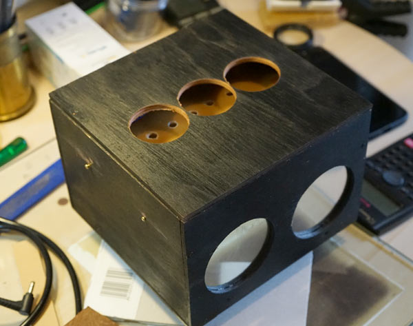
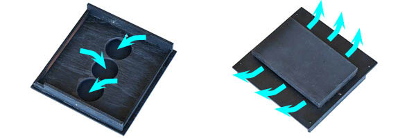
Finally I cut a lid that has a frame underneath so that it fits inside the box. The holes at the top are a vent for heat dissipation. A flapped lid was placed over them, taking care to avoid light leaks, but allowing the hot air to flow out.
Negative Carrier
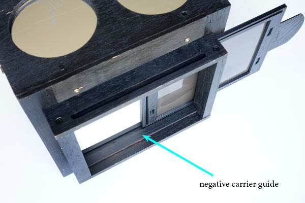
The base of the box provides an upper guide to the negative holder, but it is interesting that you also place a lower guide by gluing it to the frame that attaches to the camera. A 3 mm thick clapboard, marked in the photo as a negative carrier guide, solves this problem.
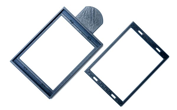
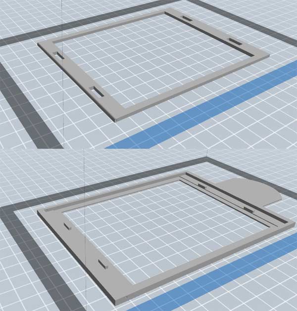
The film holder itself is just a double frame that must hold the film in the center and flat position. It can be done by cutting some plastic, PS, PVC or acrylic sheets. But it can also be printed in 3D. Many workshops are offering these services at a reasonable price. If you choose 3D, choose ABS material that is more resistant.
In the aforementioned file apenasimagens_led_rgb_V1.zip you will find .stl files that are negative carriers designs, for 4×5 ” ready for printing. Before printing, check if the measurements are correct because your box may show some variation in relation to this one I did it even though you used the same measurements. If necessary, ask the 3D printer to make the adjustments. Once you adjusted it, use this 4×5 as a basis to draw for other formats.
This ends the construction of the box. As always, on homemade projects, it was produced according to the tools, materials and skills I could use. The end result is that the PCB hovers above the diffuser, distributing a uniform light, light leaks are negligible and the assembly is light and can be easily attached to the back of the camera. It was tested on a Linhof and a Toyo 4x 5 “.
There are many sets of RGB LEDs already assembled in some configuration and they usually come with a remote control using infrared. But as the controls offered are very limited and as the physical distribution of the LEDs is critical to offer uniform light over the diffuser with a size predetermined by the ¼ plate, I decided to engrave a plate designed especially for this project.
There are firms that produce PCBs for prototyping in small quantities and even a single copy. Using one of them can save a lot of time and work. The circuit design can be found in pdf in the file apenasimagens_led_rgb_V1.zip. I included there this one featured in this post and also a second one for medium format – having only 12 LEDs. I don’t know if those producing PCBs accept .pdf but if not, there must be some type of converter for the format they use. Some research is needed.
But if you are the type that likes to do it yourself, here follow the instructions. I am assuming that as you are thinking of making a photographic enlarger, analog photography with its chemical processes with acids, alkalis, oxidizers, carcinogens, allergens and other hazards of metier, are under your control with the use of personal protective equipment for skin , eyes, breathing, ingestion and that you know how to avoid / mitigate a possible harmful event. If you are a novice and do not have the training / information necessary to deal with these processes: DO NOT make your board. Send it to someone who know how to do it. Its preparation involves dangerous reagents.
I saw many very different tutorials on the web teaching how to perform the procedure. I chose the method that uses a blue film called dry film. If you search for dry film pcb you will find it for sale. It is sold in small quantities and the cost is quite modest. I tried the method of laser printing on plain paper and transferring the design with an iron but was unsuccessful. In general, the dry film process is as follows:
Materials:
Photolith with the PCB design.
Plate: 165 x 170 mm (check your box and give a clearance of 2 mm). It is a plastic or resin base covered with a copper layer.
Dry film enough to cover this board. It cannot receive light and must be kept in a black bag and preferably in the refrigerator.
Darkroom photo trays.
Sodium Carbonate. You should already have this one in your darkroom as it is the most used alkali in photography.
Sodium hydroxide (caustic soda). This one must already be in your darkroom too, it’s the strong alkali.
500 ml of 42% Iron Perchloride solution. This one you will probably only use to make PCBs. It is usually sold in electronic component stores.
How it works
The dry film is applied over the copper of the plate and the photolith goes over it. Then it is exposed to the sun or another source of UV light. The parts that receive light darken. The parts that do not receive light remain clear and soluble in a sodium carbonate solution. The board is bathed, thus exposing the copper of the plate to the parts that have not received light. Then it is immersed in the iron perchloride solution and it will attack the copper removing it completely on the not protected areas. As the tracks are still covered by the dry film, the plate must be placed in a sodium hydroxide solution to remove the dry film that has darkened / hardened, thus finally exposing the copper tracks that form the circuit. To finish it is necessary to drill the holes where the wires and components will be placed. Watch the video to see the end-to-end process.
Procedure
Make a photolithographic film with the circuit. Some printshops make the photolithograph from .pdf files. But avoid things done with ink-jet, laser or bases that are not transparent like acetate. Ask to see samples before having yours done. It must be a material like the one in the photo above. It is very important for you to point out to anyone who is going to make the photolithograph that it needs to print in its original size, 100%, without increasing or decreasing.
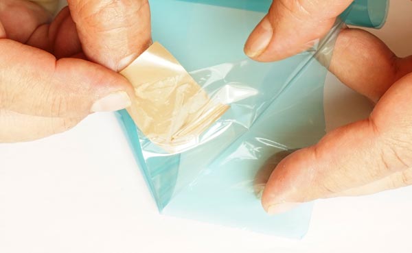
In low light, remove the protective film from one side of the dry film. The light-sensitive part is the blue layer. But it is surrounded, on both sides, by a transparent film that needs to be removed to apply the dry film on the copper surface. It is a little difficult to do this because the materials are very thin and malleable. I found that applying a piece of adhesive tape to one end and pulling it, this task can be performed more easily. That’s what I’m doing in the photo below.
Dip it in the water along with the plate. Gently lay the dry film on the plate and with your fingers start to expel the water between them. Ideally, the dry film should be 3 to 5 mm smaller than the plate. Just enough so that there is no leftover.
When it is already solidary with the plate, it must be removed from the water and with a cloth, or in the ideal case, with an engraver roll, expel the water between the dry film and the plate. The dry film should be as if glued to the plate and without bubbles or irregularities.
Put in a dark place to dry and wait 48 h.
Inspect the quality and uniformity of dry film adhesion. If there are failures, it is better to remove it with sodium carbonate solution (see step 7) and restart the process.
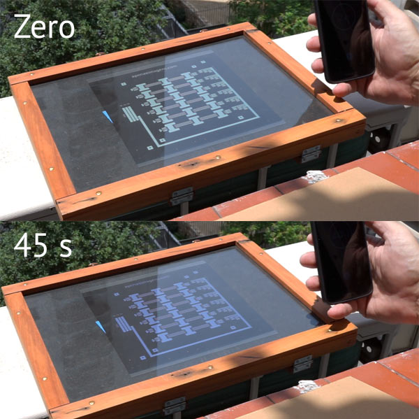
If the adhesion is good and uniform, place the photolithograph on the dry film, pressing it with a glass plate. A contact printing press is ideal. The photolith has its right side. apenasimagens.com must be legible to make sure it is in the right position. Expose to the sun until the blue is dark. In very strong sunlight it takes only 45 s. The danger of overexposure is that the thin spaces between the tracks also start to harden and the sodium carbonate solution cannot completely remove these partially hardened dry film interstices. Do not overdo the exposure.
After exposing the sign, check that the design is very clear and that dark blue does not invade areas that should be clear. If OK, dip the plate in a solution of sodium carbonate (10g in 1 liter, or follow your supplier’s instructions) and observe that the light blue begins to dissolve. You can help with a very soft brush. Don’t be afraid to overdo this cleansing bath. But be careful not to pluck the dark blue mechanically. This can happen if you use a sponge that can curl up on the ends of protected trails. If the solution gets too cloudy you can exchange it for a new one. I normally use two baths in sodium carbonate. The risk of not completely removing the light blue dry film is that afterwards the iron perchloride will not remove the copper leaving the tracks that should be apart in contact.
At this point, you can still go back and start again without losing the board. Make sure that the copper is really clean and bare at all points outside the tracks, especially between them. In case not, go directly to step 10, that is, do not corrode the copper in the iron perchloride, instead clean the entire dry film and start again.
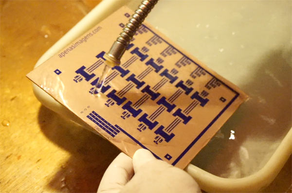
After successfully removing the dry film that was not hardened by light, the plate is immersed in the iron perchloride solution that should be used as it comes in the package, without any extra dilution. This bath takes time and depends on the agitation. Ideally, the tray should be swinging but the complete dissolution of the copper may take 40 minutes or more. The iron perchloride can be reused and so must be returned to its flask. Although the perchloride looks horrible, the plate and tray can easily be washed under running water.
At this point, only the dry film cover that protected the tracks remains to be removed. This is done with a sodium hydroxide solution (30g in 1 liter, or follow your supplier’s instructions). After a few moments the dry film starts to come off. Just gently shake the tray taking care not to spill the solution where it should not, after all, even though it is not a strong solution, it is caustic soda. This solution must be discarded.
hen just wash the plate well and check that there is no short circuit. This can be done with a multimeter or a 3V battery and a small LED. If some trails are bridged by remaining copper, it is still possible to correct by scraping copper debris in unwanted places with a stylus or something similar. But if you have followed the procedure so far this should not happen.
I was asked about the device featured in the video, the one that rocks the tray. It is very simple and I believe the following short video explains it all.
Finally, the plate should be drilled in the places marked with a 0.8 mm drill. Such drills are easily found in stores that sell plates for PCB, iron perchloride, soldering and electronic components. It can also be found online at the same suppliers for electronics.
Be sure to watch the video as it will complete your understanding of the above description.
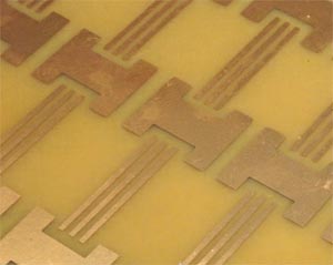
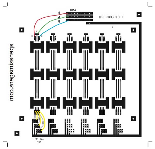
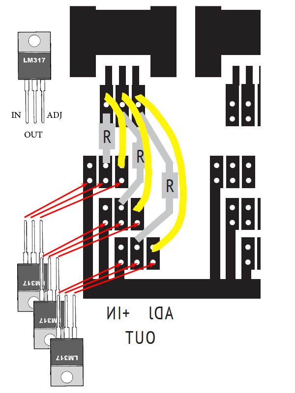
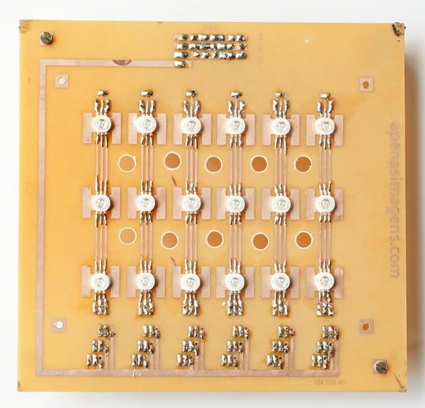
The board is now ready to receive the components. The LEDs are placed on the face that has the tracks and the other components on the opposite side. The power supply chosen is 12 V and 10 A, as this is a very easy source to find. At this back to table of contentsge LEDs are arranged in series circuits of 3 LEDs. That is why in the board design, above, we clearly see that there are 6 identical groups of 3 LEDs each. The writings are reversed because we are seeing it from the opposite side of the tracks.
In addition to the LEDs, there are two components on this board, a resistor and an LM317. The LM317 is a current limiter and serves to prevent the current from rising too high and end up damaging or burning the LEDs. It is very important to take into account its position so as not to invert + IN with ADJ. It has an input that is the positive 12 V pole, coming from the control box, and is distributed to all LM317 directly. It is the trail that goes around the right in the drawing above (the entire plate) and serves all LM317. But the power + of the LEDs comes from the OUT pin, the central pin of the LM317, passes through the R resistor and is in contact with the ADJ (adjust), which is the pin that will regulate the current according to the resistance value R. For 3W LEDs (1W per color) and 12V / 10A source, the resistance value is 3.9 Ω.
The three tracks that arrive at the LEDs underneath (in the drawing above) are therefore positive and already duly modulated in a safe current range for the LEDs. Each corresponds to a Red, Green and Blue color.
At the top of these three tracks, after passing through the LEDs, they are connected to ground (GND) in the control box. There are therefore 4 wires that connect the head to the control box. A common positive of 12 V and 3 “different” GND, one for each color. This can be a little strange because GND is also called “common” but here what is common to all is +. The point is that each GND will still pass through the TIP120 (explained below) and only then join to the final and common GND. In fact, it is not exactly a ground, like a ground that we connect to Earth, it is more the negative of the circuit. But we don’t need to go into those details.
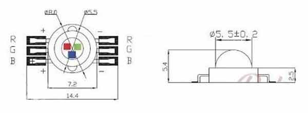
The LEDs chosen are 3W RGB, with 1W for each color. 6-legged LEDs were chosen, that is, a + and an – independent for each color. The circuit does not work if you buy a 4-legged RGB You would have to redraw everything. They are easily found online and are probably all the same. Anyway, here follows a more detailed specification for the ones I used in this specific assembly:
1 – Dimensions in mm:
2 – Power: 3 W
3 – Forward Tension: R: 2.0-2.4 V G: 3.2-3.4 V B: 3.2-3.4 V
4 – Forward Current: R: 350mA G: 350mA B: 350mA
5 – Luminous flux: R: 30-40LM G: 80-90LM B: 30-40LM
6 – Angle: 140)
7 – Working temperature:-20ºC to 60ºC
8 – Wavelength per channel: R: 620-625nm – G: 520-525nm – B: 460-465nm
9 – Expected shelf life: 50,000 Hours
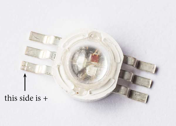
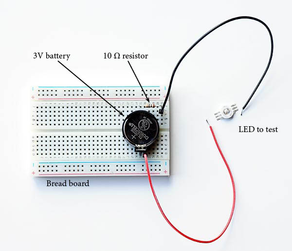
The LEDs have polarity and before soldering them it is very important to check each color on each one and be sure about the right position. On one of the legs comes a + mark (above) but the best is to test with a 3V battery, like a DL2026.
The circuit is simple and can be assembled quickly with a small breadboard as pictured above and a battery holder. They are sold in stores that work with Arduinos and robotics. Just plug in the 3V battery holder, the type that is soldered in PCBs, connect a 10Ω resistor in series and see if the led lights up when it closes the circuit.
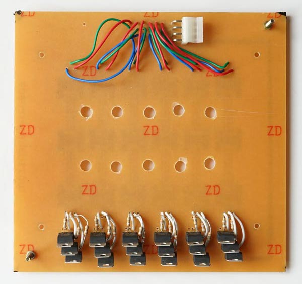
In addition to soldering, LEDs need to receive a little bit of thermal paste to improve heat transmission. These type H shapes that are on the plate and do not bind with anything were thought of as heatsinks that receiving heat from the LEDs and increasing the area of contact with the air, should be able to dissipate something. That’s why you must apply the paste.
Be sure to watch the video. It goes without saying that I am not a soldering expert, the welds are ugly and irregular. But at least in the video I show how I did it and if you do the same, even if it is not the most beautiful way, it will work too.
RGB LEDs and color paper
Everything that has been said so far has been designed for black and white papers. The colored enlargers, which I don’t know well, have heads with three colors: magenta, yellow and blue. This is because the light source is white, and the filters will subtract colors from this very “rich” initial matrix produced by dichroic lamps. The head built through this tutorial uses a principle of “adding”, not subtracting, colors through three basic RGB colors, which are quite “poor” individually, that is, individually they present a very narrow range of the spectrum. But the final mix can possibly made close to the final mix of a conventional color magnifier. It is a matter of adjusting the parameters of the three colors so that a light that results when crossing the color negative produces an image that is correctly read by the paper and its development process. But as I don’t use colored films and papers, I didn’t even think about trying, not out of logic, experimentation or trial and error, to formulate a mix of colors that would make it possible to use this head to produce color copies. Colorimetry is one of the most complex areas of technology as it lies somewhere between science and psychology of perception. There may already be documentation and knowledge about it, but I haven’t even researched it.
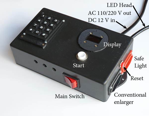
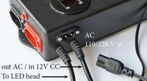
The control box is connected to AC 110 or 220 V power (depending on the source you buy). It has a 4-way wire that goes back and forth to the power adapter, one pair takes AC power and the other pair brings 12V DC power. It would also be possible to connect the source on the wall and the control box simply on the adapter. However, in this case, I thought the system would have two on/off switches, one in the box and one at the source.
To have only one switch, which turns everything off when you turn it off, this arrangement was chosen. So the main power input is in the control box as shown in the photo. The other cable coming out of the control box is the one that goes to the LED head and, as seen above, has 4 ways. The currents are not very high but go well beyond a mere logical signal. So choose more robust gauge wires.
The control box has two functions: it is a timer and an RGB color mixer. As a timer it allows you to control how long the head will be on. It does this with 1 to 9 flashes of up to 99 s each. It is true that we do not use such long times but with two digits … we can go up to 99, so let it be. In addition to controlling the LED head, a common socket has also been incorporated that can control a conventional enlarger. It also controls a safelight or a safelight circuit up to 10A. I also use RGB LEDs as a safelight in my lab, by turning on only red.
In the mixer function, the control box allows you to vary the proportion of RGB colors. Multi-contrast papers have the least contrast when they are illuminated with green light. In this case, only a sensitive layer is activated. They present the maximum contrast with Blue light, when more layers are activated, usually 3 layers. The greater number of layers makes the density rise faster and thus increases the contrast.
Some people find it strange that it is just a combination of green and blue since the paper manufacturers’ multi-contrast filters apparently have nothing to do with these colors. The reason is simple to understand. In a conventional magnifier we start with the “white” light from the lamp and the filters must cut something off. When they cut the blue or the green, in both cases the red and its surroundings still pass and that is why the filters have those colors more in the range from magenta to yellowish. In addition, the spectrum of incandescent lamps is very rich and goes far beyond the narrow colors present in RGB. But the fact is that for photographic paper, the colors that count are green and blue, basically, and the use of RGB LEDs showed that only with these two colors is it possible to vary the contrast of MG papers.
Components
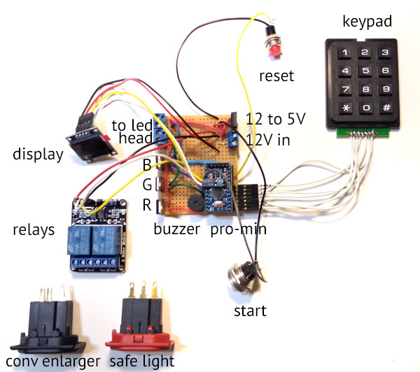
Depending on the box you choose it can be a good contortion exercise to put everything in it. In the picture above we can see the components all scattered and it is easier to identify them and talk a little about their functions.
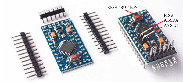
Arduino Pro-Mini Atmega328 16mhz 5V – this is the microprocessor, it is the intelligence that will control everything.
5V Buzzer – Although almost all operations involve visual changes: the display, the enlarger lights and the safelight, it is very important to have audible signals as confirmation that something has really happened. This buzzer gives you some alerts that you will soon get used to interpreting and will have greater security about operations.
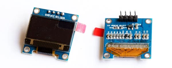
Oled Display – This is a small white light display that still needs to be covered with a red film to make sure that its light will not affect the papers. It tells you what the head is programmed to do when the start button is pressed. It also reports some current settings. See the user manual in the image-only_led_rgb_V1.zip file
Keypad – this is a 3×4 keyboard that uses 7 wires connected to 7 pins of the Pro-Mini. Attention to the fact that in the photo they are all in sequence in the Pro-Mini but in the final project they are like 3, skip one, 4 pins. That is because I forgot to avoid using pin 13 and the picture as already done. This pin is connected to an internal LED on the Pro-Mini and ends up giving an error if we try to use it. In the final project, the keyboard is connected to 10, 11, 12, 14, 15, 16, 17, that is, skipping 13, different from the photo above.
Reset – this button resets the Pro-Mini. Can you imagine Windows without CTRL + ALT + DEL or Mac without Force Quit? Well, sometimes, for an ignored reason, the Arduino also gets lost and needs to be restarted. It is due to energy problems. Do not worry about it. It happens, but the frequency is low and Reset fix it.
Relays – These are switches which receive a logic signal from Arduino, a weak signal, but with this signal they can turn on and off high power circuits with up to 10 A of current in this case. The wires connecting them to the Arduino Pro-Mini are shown in the photo and the 6 pins at the bottom are connected to the safelight and conventional enlarger sockets, which would be a common enlarger if you have one in your darkroom. These wires are not shown here.
TIP120 – Indicated by BGR are three Tip120, these are components similar to relays, in the sense that with a logic signal they are able to release energy to a high power circuit. In this case, the LED circuit. The difference is that relays use solenoids, springs and physical switches, while the TIP120 uses solid state electronics to turn a second circuit on and off. This is necessary in this case because to vary the power of the LEDs the Arduino sends a logic signal that is not continuous, but rather modulated, that is, intermittent, with a frequency high enough to not allow mechanical switches as in relays. It is thanks to these intermittent signals, PWM (Pulse Width Modulation), that we are able to mix blue and green and use multi-contrast papers with the LED head.
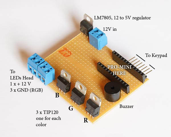
To led head – The TIP120 provide the ground, for the LED head, for each of the colors. The LED head wires are connected to the blue connectors that appear at the top of the board on the left. The fourth connector is the 12V positive that comes directly from the other blue connector, at 12 V in.
12 V in – This blue connector receives the + and – directly from the 12V supply when everything is connected.
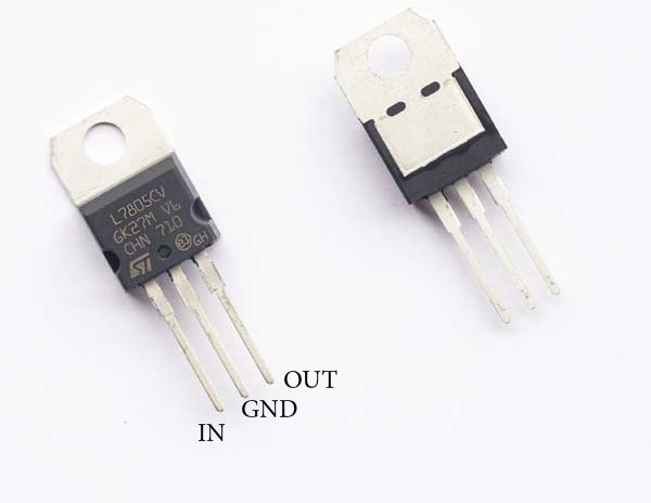
12 to 5V – This is an LM7805 that takes the same 12V source that will power the LEDs to also power the Arduino-Pro Mini which is 5V. It has 3 pins the ground is common and entering 12V on one of them you collect 5V on the third pin. It is very convenient, but it is also possible to use a separate 5V supply as long as the ground is kept common to all.
Universal PCB
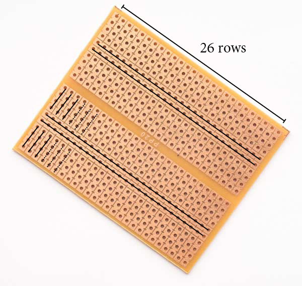
For mounting the main board of the control box, it is not worth producing a specific PCB, instead it is better to buy a standard PCB of the type that has two center tracks and two sets of 4 holes connected, one on each side, as indicated in the photo above by the black lines. The plate shown in the photo has two groups of 26 holes. But it is possible to adapt to a different layout provided you keep the same connections. The distance between these holes is standard so that the components are manufactured at the same pace and fit perfectly into the holes. If you can’t find one exactly like this, buy a bigger one that can be cut and yield the same result.
ATENTION: In the above picture the TIP120s are erroneously rotate by 180º. I will fix it as soon as the COVID-19 confinement allows me to buy more components and take a new picture.
Do not solder the Arduino directly to the board. Instead, solder two pieces of female 2.54mm header socket single row strip PCB connector, like the ones shown in the photo above. To connect the keypad, use a male PCB single row straight or right angle header strip connector. The photo shows a right angle as it was more suitable for the lay-out of the box that was used. Note that 8 pins were placed but the keypad uses only 7. This is because pin 13 is free. I believe that if you take this photo on your cell phone to a specialized store, or send it to an online store, you will go out with, or receive, everything you need.
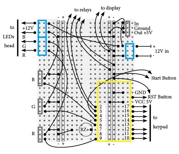
In the diagram above are all the wires that need to be added. The yellow frame is the Pro-Mini and the numbers are the pin numbers. Note that pins 14 through 17 are marked on the Arduino Pro Mini as A0, A1, A2, A3. The blue frames are connectors. The three grays marked with RGB are the TIP120. BZ is the buzzer that for convenience will be plugged directly into the board. The wires are indicated in black and the balls are their solder points. Use the thickest wire possible but still fitting into the holes in the board. Especially in the case of the wires that go to the LEDs. For the indications to relay, to start button, to display and to reset button cut wires according to the size of your box. But consider that it is better to err for more than less and wire does not cost much. Avoid having to make amendments later or having to redo welds.
For the Oled Display, only the + 5V and Ground (GND or -) wires are indicated. The signal wires, Rx and Tx, come out of the middle of the Arduino Pro-Mini board where they are marked with A4 and A5, see below.
It is good practice to use colors with some logic in these circuits. Usually black is reserved for Ground (GND). Red for +, 5 or 12V in our case. For RGB circuits it is quite evident that using Red, Green and Blue makes perfect sense even if it is worth repeating Red (maybe a different shade of red, if available). For the start, reset and relay buttons, use colors like yellow, brown, gray or violet.
More detailed view on components
Arduino Pro Mini Atmega328 16mhz 5v
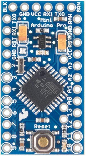
I think that to occupy less volume it comes without the pins, as seen in the Pro-Mini on the left. The first step is to solder them. Start with A4 and A5 in the middle of the board. The big ones are the pins that the Arduino uses in its normal operation and the ones that are on the smaller side: BLK, GND, VCC, RXI, TX0 and GRN, are for communication. It is through the latter set that the program is loaded. Note that the large header strips are with the long pins down while the communication set has the long pins up. I don’t know why, pins A4 and A5 don’t come in the package with the Pro-Mini. You need to buy singles. Once prepared in this way, the Arduino can be plugged and unplugged from the board.
Display Oled 0.96 Spi – White
The display uses only 4 pins as it works with the I2C protocol for communication. The SDA and SLC pins are connected to pins A4 and A5 of the Pro-Mini, respectively. The Vcc pin is connected to + 5V and GND which is the Ground, goes to the negative of the board. This order may vary from one manufacturer to another. Check yours. Also keep in mind that after screwing the display onto its frame, you will probably no longer be able to read the pin marking. Not it down before making your fixation.
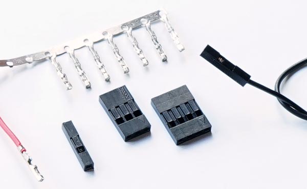
You will need to prepare some wires with terminals, called jumpers. There are ready made jumpers but they have a fixed size and the wire is in general very thin and of very poor quality. I prefer to buy separate wire and terminals and make the jumper with solder and in the size that I will really need. In the video I show how I do it. It is easy after some practice and is very satisfying.
It is possible to buy single terminals, a single pin, and also in sets. In this project, having a quadruple and a triple (as in the photo) is interesting because the keypad will also need jumpers. As there are 4 rows and 3 columns on the keyboard, you can assemble the cables in an organized way.
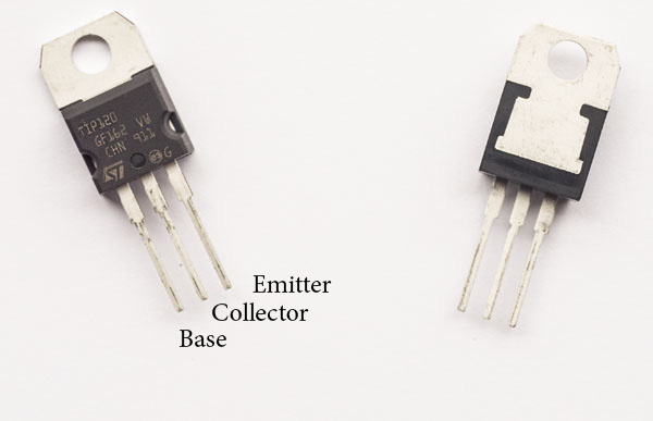
TIP120
The TIP12o is the component that receives a logic signal (weak 5V) from the Pro-Mini. When this happens, it releases the current from the higher power circuit, the one that has the LEDs and works at higher back to table of contentsge (12V) and higher current. It has 3 tips: Base, Collector and Emitter. The Base is the one that receives the logic signal and is therefore connected to a pin of the Pro-Mini. The Collector is what “collects” the current from the LEDs. Remember that they are all directly at + 12V and their negative pole is taken to the Collector. As the current does not die there, it will be “emitted” by the Emitter who will finally dispatch it to the ground, where sooner or later the circuit would ever end. It is like a faucet that is opened by applying a back to table of contentsge to the Base. When this happens, a large current is released to flow from the Collector to the Emitter.
The TIP120 is sold in a few different presentations. The one that was used in this project is the TO-220 and is very easy to find. But it’s worth checking out this code or a photo to make sure it’s the same format.
Just to remember, the Arduino pins that are connected to the Base are special. They are of the PWM type, that is, they emit an intermittent signal and thus regulate the energy released by the LEDs. They actually blink. But they blink so fast that we don’t notice.
back to table of contentsge regulator L7805
The back to table of contentsge regulator is very intuitive. There are three pins, GND has to be connected to the general GND since the ground is common. IN receives + 12V and in OUT we have + 5V that will feed the Arduino Pro-Mini. The display, the beep (buzzer) and the relays (relays) are also 5V. But these are all connected together on the Arduino VCC pin. The maximum current that the LM7805 can support is 1.5A.
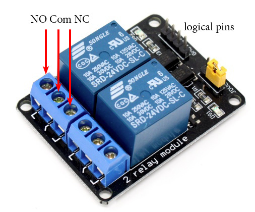
Relays
This point deserves more attention. The relays are connected to + 5V and to ground. The + 5V logic signal comes from pins 2 and 3, so there are 4 cables connected to the Arduino board. What is not very intuitive is that in these relay modules the solenoid is activated when the Arduino pin is grounded and not when it is energized as we could expect. It is when we cut to zero the back to table of contentsge on the logic pin that current will flow inside the solenoid. If we add to this that it is not good for the solenoid to be energized for a very long period of time, and we have the clue for a strategy on how to connect the relays.
The relays on this timer are set to support: one darkroom safelight and one conventional enlarger. Considering that the safelight stays on practically all the time, that it turns off only when we are focusing/framing a negative and that the light from the conventional enlarger only turns on when we are focusing or exposing a photograph, the ideal combination is:
activated solenoid
deactivated solenoid
safelight
off
on
conventional enlarger
on
off
The three pins that perform the function of switches, controlled by the relay, can be configured to provide exactly the situation as in the table above and thus minimize the time that the solenoids are energized.
The central pin in each block of 3 is called a common pin and is like an “input”. This input is always connected to the pin called NC. NC means normally closed. This means that even with the relay completely disconnected, the Com and NC terminals are closed and allow current to flow through them. The NO terminal, which means normally open, is always open, does not pass current through them unless the solenoid is energized.
The solution then is to connect the safelight on the NC and the enlarger light on the NO. Some relay modules have exactly COM, NC and NO written on them, others use symbols like the one in the photo above. But, in any case, if the behavior is not as expected, just reverse it.
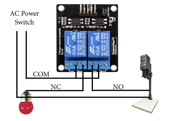
This part of the circuit should look like the diagram above. From the main switch (AC Power Switch), connected to the 110 / 220V socket, a wire goes directly to the safelight and also to the enlarger. The other wire goes to the two common terminals on the relay modules. The second wire of the enlarger is connected to the NO, normally open. The second wire of the safelight is connected to the NC, normally closed.
Keypad
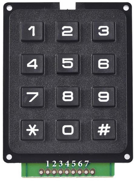
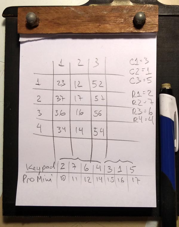
There are membrane keyboards but I think that, especially for use in low light, those with keys are more comfortable. Each time a key is pressed, two of the terminals marked 1 to 7 are closed. You need to find out, if it is not included in your keypad documentation, which terminals determine the three columns and the three rows.
Make a 3×4 table like the keyboard and write down in each cell, corresponding to a key, which is the double terminal that closes when it is pressed. I don’t know if this is standardized on all 3 x 4 keyboards, so I can only say to check it out.
In my case, the keyboard came without any information. I did the test and produced the table above. When I pressed key 5, for example, I closed terminals 1 and 7. When I pressed key 9, I closed 5 and 6. After filling in the table, it was easy to see that terminals 3, 1 and 5 correspond to columns and terminals 2 , 7, 6 and 4 correspond to the lines. I then mounted a triple terminal with 3-1-5 and a quadruple with 2-7-6-4, and connected the two on the Arduino Pro-Mini as shown in the second table.
If the numbers you enter do not correspond to those on the screen, you must change the order in these groups of 3 and 4 pins. But it is not necessary to do this on the wires themselves. This is configurable on the sketch lines. See more below in Sketch, configuration.
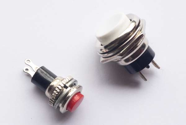
Push buttons
The only advice here is to use a Reset button very different from the Start and place them far away one to another in your box, to avoid exchanging each other during the operation.
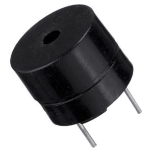
Buzzer
Buy a 5V buzzer that can be plugged directly onto the board. There are several sizes, but the one that has approximately 7.5 mm between the pins is one that occupies exactly 3 spaces on a standard board. Also pay attention to polarity. The positive goes on the Arduino pin and the other on circuit’s GND. Unless specifically stated otherwise, the longest pin is the +. If you reverse the polarity it will not tune.
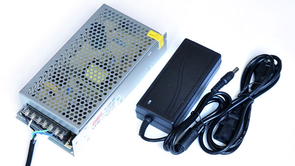
Power adapter 12V/10A
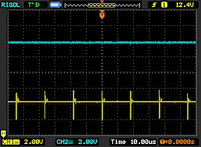
There are several models of 12V / 10A power adapters. As I started my projects with some like the one on the left and they worked well, I kept buying them. But there are more compact ones like the one on the right. 10A it is a little over-sized for this project. But the price difference does not justify choosing one with less amperage and there are not so many options on the market. Below 10A there is usually 5A and this is a little fair.
Try to buy from a good supplier. Almost all the problems that appear on the Arduino are the result of power supply that fluctuate a lot. None provides accurate 12V all the time, but some go smoother and others have spikes that make the microprocessor get lost. Just to illustrate, above we have images captured on an oscilloscope. Blue is the adapter on the left, yellow the one on the right, in the photo above. Note that every ~ 20 µs the adapter on the right gives an oscillation of almost 4V while the other is much more constant in this resolution. Maybe this does not affect the Pro-Mini or LEDs behavior, but for sure the blue line is a nicer one.
The box
All these components, the board and the keyboard must obviously be arranged in a box. Standard boxes for prototyping and small productions are sold in specialized stores. They are usually made of ABS or some other plastic material. It is also possible to build in wood or metal. This part I will leave open because it is very dependent on what the person who is going to set up the project has available, what tools he/she has and especially the types of materials with which he/she feels more comfortable to work with. The box I used has internal dimensions: 45 x 100 x 180 mm and it was very tight. If you search online for “plastic box for electronics” you will find a thousand options. Better to err for more than less.
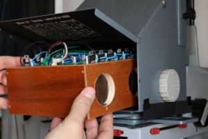
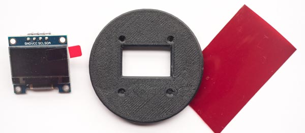
One point to consider is the assembly of the display. It can be secured with 4 M2 screws and nuts. But if you press beyond a certain point and compress the display, it can break and render it unusable (this has already happened to me). To avoid this problem I designed a round frame (photo above) that has the hole in the correct place, the window for the display, a slot for a red film and supports for the small PCB that prevent the pressure of the grip from falling on the glass. This frame adapts to a round hole in the box, easy to make with a cup saw, which is 46 mm in diameter. The frame is simply glued to the box. In the file apenasimagens_led_rgb_V1.zip you find the file display_frame.stl to print a frame like this.
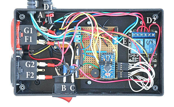
Energy flow
AC 110 / 220V energy enters through the point marked A. Then the two wires go directly to the central point of the general switch in B. When this switch is closed it energizes the two poles in C. From C, we have two wires that lead power to the AC / DC 12V adapter on D1. Still from C, one of the poles goes straight to the safelight and conventional enlarger sockets. These are the black wires that arrive at F1 and F2 from C. The other pole from C goes to D2, and energizes the two relays. When these perform their function as switches, they deliver or cut the circuit in G1 and G2. Finally, the AC power that went to the adapter in D1, returns as DC 12V and will supply power to the logic circuit in E through the green and blue wires. This is the entire power supply flow in this project.
The program that controls the entire operation of the timer and as a consequence of the enlarger head with RGB LEDs is called in the Arduinoland language as sketch. I will try in this tutorial to make it so that someone can blindly load the program on their Pro-Mini without knowing anything about programming. If you know something, but not Arduino, it helps. The code in which the sketch is written is like C ++. In the file apenasimagens_led_rgb_V1.zip I include “useful links” and there you will find a series of links to go deeper into Arduino projects. I think it is very worthwhile for analog photographers. My lab is full of timers, sensors, heaters, coolers, dryers and other gadgets made with Arduino.
Even without knowing how, at least knowing what you are doing is important. So here are some explanations:
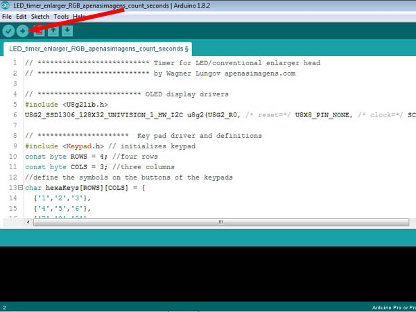
The sketch is written in text form. There is an editor/compiler called IDE which is downloaded for free for MAC and PC platforms.
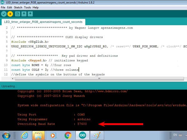
The sketch for this project is in the file apenasimagens_led_rgb_V1.zip and is called timer_enlarger_RGB_apenasimagens_count_seconds.ino. After giving file> open and opening this .ino you will have the following screen.
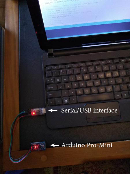
After loading the sketch you can connect the Pro-Mini to the Serial / USB interface (you will need to buy one, if you don’t have one), following the indication of the cables, remembering that the TX of one goes in the RX of the other and vice versa , VCC with VCC and GND with GND and plug the two into your computer. I use a very old lap-top, with Windows XP, exclusively for lab stuff including the Arduino IDE. It is more so as not to throw it away.
As you soldered the pins on the Pro-Mini, the names may have been hidden a little under the strip connector. Use the photo below as a reference of where GND, VCC, RXI and TXO are.
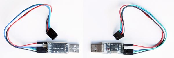
Next, a typical serial/USP or USB to TTL interface, front and back. The wires are already arranged to plug directly into the Pro-Mini following the pattern of black – and red +.
Although it is physically connected, it is necessary to check if they are connected logically. That is, if they “realized” that they are connected. The IDE is prepared to handle several variations of the Arduino architecture. You need to say which one is yours. Go to the menu and click Tools> Board and choose “Arduino Pro or Pro Mini”. Then go to Tools> Port and see if the IDE has assigned a port for your Pro-Mini. It must be COM followed by the port number. If no COM appears, try unplugging and plugging in the Serial/USB interface again. This usually works. If a COM has appeared, click on it. In the bottom right corner of the IDE window you need to check if it is the Pro Mini is there and if the COM is the same as the one you clicked and that you see in Tools> Port.
I remember that the first time I did this on my lap-top I had to change something in the Windows configuration so that it could read the interface. But that is certainly dependent on your operating system, your computer, the particular interface … in short, computer stuff. In the file apenasimagens_led_rgb_V1.zip I indicate some tutorials where you can solve this type of problem in case it happens.
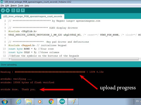
Once the physical and logical connections are made, just click on the arrow button in the screen shot above, indicated by the red arrow. The download process will start.
But before clicking, an important note. This sketch calls some libraries, with extra instructions, that hold functions used by it. There are two, in this case:
1 -The library that commands the OLES display is:
# include <U8g2lib.h> on sketch’s line 5
2 – The library that commands the keypad is:
#include <Keypad.h> on sketch’s line 9
These libraries are used a lot and are normally already loaded when installing the Arduino IDE. However, if you give the command to upload the sketch and these libraries are not present in the IDE, you will get an error message. In this case you need to include them manually. Go to menu Sketch > Include Library> Mange Libraries and follow the instructions. There is no harm, it does not cause any damage, you test the upload without knowing whether the libraries are there or not. It will only give an error message. Perhaps, by the time you are reading these lines, there is already a new IDE that, in case you can’t find it, automatically search for the online library and install it for you.
This operation can be done with the Pro-Mini plugged or unplugged to the main board of the control box (in the photo above it is unplugged, for example). But if it is in the box, do not connect the 12V source as the USB/Serial already powers the Pro-Mini.
When you click on Upload (arrow indicated above), on the IDE screen, the code will be compiled first. The friendly text of Sketch will be converted into awful machine language and there will be a check for more gross errors such as syntax, if the functions and called libraries are available and things like that. It takes a while but everything should be fine.
When the Pro-Mini was connected to the Serial / USB interface and this is on the computer, when powered up, it has already started running a program called blink.ino that makes a led associated with pin 13 turn on and off every second. The microprocessor will be busy doing this and does not know that you are trying to load another, much more interesting sketch. So, the moment the sketch is ready to download from your IDE, you need to press the RESET on the Pro-Mini, it can be the RESET on the control box, if it is there, so that it stops with Blink and starts to load the apenasimagens_LED_head_sketch_V1.ino.
The exact time to hit RESET is a little tricky for beginners. Keep an eye on the computer screen and fingertip on RESET button while the IDE compiles and verifies. It will write a few lines on the screen and at a given moment it will write:
Using Port:
Using Programmer:
Overriding Baud Rate:
This “Overriding Baud Rate” I think may not come because maybe IDE will decide not to overwrite its Baud Rate at that time you press RESET. If it was the right time you will see a progress bar made up of ##### indicating that the program is being sent to the Pro-Mini. It is very fast. It will end with a Thank you.
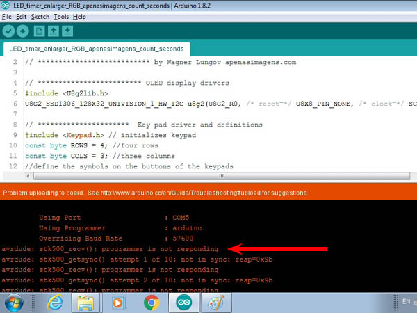
If something went wrong you will see:
The IDE will try 10 times to upload. Theoretically it is still possible to have the luck of pressing RESET at the right time, during these 10 attempts, but I almost never managed to hit this in good time and so I adopted the procedure to wait for the 10 attempts to fail and start again by clicking upload in the IDE.
A first test that you need to do is to see if the numbers you type appear correctly on the screen. If not, you will need to change two lines of the sketch. See below where this should be done in Sketch, configuration.
In case everything is all right, remove the Serial / USB interface and, if not already, plug the Pro-Mini on the main board inside the control box, read the quick guide that is in the apenasimages_led_rgb_V1.zip, prepare the trays, papers, negatives, turn on the main switch and print some pictures.
Once you have mastered the process of uploading the program and found that it is running in the “factory” version. Go back to the IDE, there are things you can configure for a more customised use of your new timer and LED head.
All sketch lines that start with // are comments and have no effect on the Pro-Mini’s behavior. In these lines I have placed instructions on what can be modified. Never delete these two slashes or the sketch will try to compile the line and will give you an error message. The items that you can change are the following:
Lines 18 and 19 are provided with the Pro_Mini pin numbers that connect to the keyboard. It may happen that due to some confusion in the order of the wires the typing is not correct. The easiest thing is for you to change the order of the numbers {14, 15, 16, 17} and {10, 11, 12}. The numbers are these, as they are the pins where you connected the keypad, but perhaps in a different order.
In line 39 you see t_off = 2500. This is the time between two flashes of the enlarger. It is enough to reposition a mask when preparing test strips, for instance. If you find it too short or too long, change this value. It is in milliseconds, that is, 2500 corresponds to 2.5 s.
In line 46 you see head = 0, this defines which enlarger head the timer will start commanding. Leaving 0 it will assume that you want the LED head as the default, if you put 1 it will be the conventional enlarger head that will go as default. In any case, you can switch during the operation by pressing * 3.
In line 47 you see precision = 0, this means that the precision of seconds will be default and each flash can last from 1 to 99 seconds. If you prefer the default precision of tenths of seconds with flashes from 0.1 to 9.9 s, set precision = 1. To switch between modes during operation, type * 2 .
In line 51 you can choose whether you want the default focus to be white or just red. With * 4 you can change this at any time. But if you override focus_wr = 0 with focus_wr = 1, the initial state will be red. If you use an easel you will probably prefer white light. But if you want to be able to position the paper while projecting the image, then the red light will allow this maneuver as it does not impress the paper. But it’s a good idea to do a test to make sure of that. Especially if times are long.
In lines 61 and 62 you have the recipes for mixing blue and green that will vary the contrast of the paper if you use multi-contrast paper.
contrast
blue
green
0
0
252
1
9
224
2
19
196
3
28
168
4
37
140
5
46
112
6
56
84
7
65
56
8
75
28
9
84
0
When programming an exposure in the timer, the first information provided is the desired contrast. It can range from 0 to 9. Zero is the lowest contrast and 9 is the highest contrast. Lower contrast means only green LEDs lit and the greatest contrast occurs with only blue ones. You will not see these colors as the reds also light up to assist in viewing the projected image. In the table above you have the way in which the intermediate levels are programmed. When increasing the contrast, the blue grows and the green decreases.
The reason why the maximum for green is 252 and for blue is 84 is as follows: these values can vary from 0 to 255. Zero means LED off and 255 on at the maximum power that the circuit allows it to supply. But, as explained before, this power is the result of an intermittent LED. The pins with variable power of the Arduino Pro-Mini cause the signal to flicker with zero signal and 255 continuous signal. A value of 128, for example, means 50% of the time on and 50% of the time off, that is, it is half the power. But when it’s on, it’s always at full power.
Fortunately, for an LED the oscillation frequency of these pins does not affect the performance of ascents and descents (like an incandescent lamp that needs time to warm up and takes time to cool down because the light is a by-product of temperature) and we can count that 128 corresponds well to 50% of the power. This explains the scale linearity that appears in the green that starts with 28 and adds up to 28 at each step.
The blue scale does not go up to 255 for the following reason: The contrast in multi-contrast papers is made with emulsion layers that are only sensitive to green or green and blue. Only in green we have a single layer out of a total of generally 3 layers. So, it is to be expected that, with the same power, the blue light will increase the density much faster because there are 3 layers responding instead of just one. I noticed in my first tests that green actually needs a lot more time to reach a medium gray. For that reason, to balance things better. I limited the power of the blue to about a third, varying the PMW pin only up to 84.
What you can do in this part is to modify this mix. The scales are linear, but you may want to invent softer steps in the low or high contrast region and wider steps in the opposite region. You may want to create a table that simulates conventional multi-contrast filters. I’m just leaving it open. I’ve been using the table for like 3 years now and I got used to it. I must say that with this table I still have to decrease time as I increase contrast in order to balance the overal print density. Ideally one should try to figure out a table in which at least middle gray could be achieved with the same time/aperture in whatever contrast leve. But I did not bother trying to accommodate that, as I said, I simply got used to it. With practice I could develop a good gut feeling for the effect and compensations needed when changing the contrast.
Anyway, consider that both ends are fixed: only green or only blue. The mixed proportions it is possible to change according to operator’s taste.
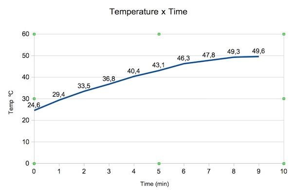
In line 64 you have: focus_power = 125. This determines the power of the focus light. As seen above, this value can go up to 255. I advise leaving half, or less, if possible, to avoid overheating. The focus with white light is the moment when the head can reach its greatest power, as the three colors are activated without the seesaw effect between blue and green, explained above. This focus_power is the variable that defines how far that power goes. In the head I built and with focus_power = 125 (half load), I measured the temperature rise in the air near the LED board, under working conditions, and found the following heating curve:
In normal use, an enlarger never stays on for that long. It is not ambient light and no one takes 9 minutes to set an image in focus. After focusing, the exposure is done in a few tens of seconds, at most, and then the enlarger is off for a few minutes while the photo is processed in the developer and following baths. In any case, here is a reminder: there is heat production! The first measure to mitigate possible damage is to keep the focus_power variable at its lowest value but still produce an image bright enough for you to focus and frame in comfort. The issue will also depend on your particular box, its materials and the geometry of the exhaust part of the hot air. Keep this in mind and note, in the worst case, you may need to install a fan.
In line 70 you have the home screen. It tells us that when you start the timer, it is programmed to show the following configuration:
cont: keep the safety light on at all times, “continuous”. Alternative would be auto, automatic. This can only be changed on the run by pressing *1.
sec: consider only whole seconds as the exposure time, without tenths. The alternative would be sec/10 to use tenths
L: consider that you are using an LED head. The alternative would be C for conventional
FW: consider that you want to focus with white light, Focus White. The alternative would be FR, for Focus Red.If you changed any of these defaults following the configuration instructions 3, 4 and / or 5 described above, don’t forget to change here too to start with a screen that corresponds to the options you have made.
These are the options for sketch parameters. You can also change the logic. I don’t know if this sketch is very well done because I have little experience with Arduinos. Perhaps it can be written in a more economical and elegant way. I tried to comment the lines well to make life easier for anyone who wants to understand how it works with a view to making changes. After editing the file, reload the Pro-Mini with your custom parameters.
Here ends the tutorial, which is more a detailed presentation of the project. Some requests from my side:
If you find any errors, please let me know so I can correct them.
If you know of anything that can be done in another way, easier, more efficient, more economical, I would like to hear your suggestion and if it is approved I will give you the credit if you wish so.
This tutorial was published in March / 2020. If you notice that something has expired, like IDE screens that have been modified, or parts that are no longer in procutcion, for example, please let me know. It is very bad for those who are following a tutorial to find information that is no longer usable.
If you are interested in providing ready-made kits with components, PCBs, or even manufacture parts or the whole of the project and sell. Feel free. If you want to advertise right here on the project page, undoubtedly the best place, contact me.
If you want to receive project updates and other tutorials/news from my website, subscribe to the newsletter. I send very few and do not share your data with anyone. I use the very popular Mailchimp platform that has its privacy policy that can be seen here.
If you made it this far, you must have noticed the work and the hours I put in to make this project available for free to everyone who still insists on continuing with analog photography. If you want to contribute to the site apenasimagens.com, here goes the “donate” button again. It’s up to you.
Documentation
Link to the .zip file with the project documentation. Thinking that maybe something is wrong or that could be improved, I will leave a record of new versions of the initial file whose name ends with V1, the following will come as V2, V3 … and a change log.
The multicontrast black and white paper uses a combination of blue and green light to obtain different grades of contrast. One layer of emulsion is sensitive only to blue and the other one to blue + green. That makes density to builds faster in the presence of blue and slower if more or only green is provided. You can check that in the MC Papers manufacturers literature.
About the enlargers, when they have a white light source, a dichroic or incandescent lamp are very common cases, then the control of light colors for color or B&W papers is done by filtering, or subtracting what is not wanted. In that case CMY filters are the ones to be used. They are calibrated subtractors. In my case I am not subtracting colors from white light because the LEDs are able to directly produce blue and green light and that is all that is needed for MC B&W paper in order to have more or less contrast in the final print.
I understood your reasoning. You would be correct if the light source would be white, the whole visible spectrum, but LEDs can produce specific parts of that spectrum so there is no need of filtering with CMY.
Brillant project!
I am working on an enlarger project as well but I am not even thinking about color for now and even the light source deep to be the most complicated part. I also started a arduino project and your documentation had helped me a lot.
Thanks
What maximum contrast index (CI) can you achieve on Ilford Multigrade papers with this type of LEDs? An why you using purple light instead of simple blue for high CI?
Hello, sorry for the late answer. I did not measure the contrast to compare the LED head x regular Multi Grade filters. But I use a Leitz Focomat enlarger for 35mm with filters, side by side with the Durst Laborator 1000 with LED head, and do not feel that it makes any difference in any direction between max contrast in each case. About the blue I used, I remember checking the royal blue x bright blue against the sensitivity graph in Ilford literature and decided that royal blue, going to a shorter wavelength region, would be more efficient.
Thank you for your answer. Indeed, haven’t yet had a chance to test the LED-head with my enlarger. I am curious how the exposing times will actually work out. Good to know that they can potentially replace a 200W bulb, thats amazing.
Thank you so much for this project! I rebuild you design and (almost) everything works as described (have yet to figure out how they keypad is correctly connected to the arduino nano).
One question: It seems to me that the LEDs are not as bright as they could be. I used 3.9 Ohms as resistors as recommended. The LEDs have the same specs as yours. Is that on purpose? When i tested a single LED with a 10Ohms resistor the LED was much brighter. Thanks. Chris.
I picked this 3.9 Ohms value in a tutorial about how to power a LED circuit. You can find it here: Series Circuits Review and LEDs. I remember that I did not want to be at the top of the current passing through LEDs. The idea behind was that in this way I would extend their life by avoiding a borderline regime. Maybe you can go a bit further, check the formula. But I can tell you that the times I use in my LED enlarger are not at all longer than what I used before with a 200W bulb in a regular condenser head.
stopping by just to thank you for the project, and an encouragement to resist the loud format amateur engineers who forget that experiment is the best part of theory.
As long as you can get an even illumination over your negative, you can use this project for any film format. I made it 4×5 because that is the size my enlarger could handle. But I think that the same number of LEDs could do a good job with 5×7, that means, the light loss would not demand a significant increase in exposure times. I say that because with 4×5″this enlarger head is really fast. Just a few seconds for a normal print.
About the flashes, it is just one way you can control contrast with Multi Contrast paper. Another way is to power blue and green with different proportions. The more blue you use, the more contrast you get. Another very interesting use of flashes is that you can easily give different contrast levels to different areas of your print. That can be done also with regular MC filters, but with LEDs it is easier as you don’t touch the enlarger.
I also made a similar head for my technika III and just discovered yours, very thourough and involved project and nice workmanship. I got by a little bit cheaper, used 94 x ws2812 leds as a strip with arduino uno which I had, existing odd ancient 10×15 glass negative carrier etc.. i’d post an image if I could.. all the best
Very cool project! I looked into doing something like this about 20 years ago, but high-output blue LED were still pretty expensive.
I love your Technica III – I have one as well.
Those are the outlets and are specific to country/region. You have to find the ones which are standard for you, so you can plug your regular enlarger and safe light circuit into them. Otherwise, any connector able to handle 110/220 V will do.
Hi, resistors are specified in ohms. This one I calculated as 3.9 Ohms. They produce a voltage drop and the power consumed is voltage drop x current. I based this circuit in the following tutorial: http://www.bristolwatch.com/sr/cc_led.htm, maybe it is better that you go through it, there you will get complete picture.
Hello, as long as you supply 12V the resistor value is the same. But, I think 5A is too little. When the 6 LEDs circuits are running with three colors turned on at about 300 mA each color per circuit, you will have 6 circuits x 3 colors x 0,3A = 5,2 A. I think it is just too tight. I may interfere in your microprocessor behaviour.Better go for a 10A power supply and have everything with some more room for unpredictable oscillations.
This whole project is brilliant – thanks for documenting it so well!
I have been playing around with LED heads for a while and have been hoping someone would develop a head using RGB LEDs.


SORRY, there are a BIG Mistake in this project: An Photo enlanger need a color head with complementar colors: CMY Ciano, Magenta and Yallow. Not RGB.
The multicontrast black and white paper uses a combination of blue and green light to obtain different grades of contrast. One layer of emulsion is sensitive only to blue and the other one to blue + green. That makes density to builds faster in the presence of blue and slower if more or only green is provided. You can check that in the MC Papers manufacturers literature.
About the enlargers, when they have a white light source, a dichroic or incandescent lamp are very common cases, then the control of light colors for color or B&W papers is done by filtering, or subtracting what is not wanted. In that case CMY filters are the ones to be used. They are calibrated subtractors. In my case I am not subtracting colors from white light because the LEDs are able to directly produce blue and green light and that is all that is needed for MC B&W paper in order to have more or less contrast in the final print.
I understood your reasoning. You would be correct if the light source would be white, the whole visible spectrum, but LEDs can produce specific parts of that spectrum so there is no need of filtering with CMY.
Thanks for this awesome Project! I brought my Ampliator Color S2, a 13×18 cm Enlarger back to life!
Brillant project!
I am working on an enlarger project as well but I am not even thinking about color for now and even the light source deep to be the most complicated part. I also started a arduino project and your documentation had helped me a lot.
Thanks
Hello!
What maximum contrast index (CI) can you achieve on Ilford Multigrade papers with this type of LEDs? An why you using purple light instead of simple blue for high CI?
Hello, sorry for the late answer. I did not measure the contrast to compare the LED head x regular Multi Grade filters. But I use a Leitz Focomat enlarger for 35mm with filters, side by side with the Durst Laborator 1000 with LED head, and do not feel that it makes any difference in any direction between max contrast in each case. About the blue I used, I remember checking the royal blue x bright blue against the sensitivity graph in Ilford literature and decided that royal blue, going to a shorter wavelength region, would be more efficient.
Thank you for your answer. Indeed, haven’t yet had a chance to test the LED-head with my enlarger. I am curious how the exposing times will actually work out. Good to know that they can potentially replace a 200W bulb, thats amazing.
Thank you so much for this project! I rebuild you design and (almost) everything works as described (have yet to figure out how they keypad is correctly connected to the arduino nano).
One question: It seems to me that the LEDs are not as bright as they could be. I used 3.9 Ohms as resistors as recommended. The LEDs have the same specs as yours. Is that on purpose? When i tested a single LED with a 10Ohms resistor the LED was much brighter. Thanks. Chris.
I picked this 3.9 Ohms value in a tutorial about how to power a LED circuit. You can find it here: Series Circuits Review and LEDs. I remember that I did not want to be at the top of the current passing through LEDs. The idea behind was that in this way I would extend their life by avoiding a borderline regime. Maybe you can go a bit further, check the formula. But I can tell you that the times I use in my LED enlarger are not at all longer than what I used before with a 200W bulb in a regular condenser head.
stopping by just to thank you for the project, and an encouragement to resist the loud format amateur engineers who forget that experiment is the best part of theory.
I struggle with the monotony of teaching 5 paragraph essays, thank you for the great ideas!!!!!LikeLike
Hello,
Is the LED illumination also usable for 5×7″ or would it be better ro some more LEDs?
I also would like to know why you use flashes of the LED instead of a permanent light?
E g. 8 sec green 4 sec. Blue
Kind regards
Martin
As long as you can get an even illumination over your negative, you can use this project for any film format. I made it 4×5 because that is the size my enlarger could handle. But I think that the same number of LEDs could do a good job with 5×7, that means, the light loss would not demand a significant increase in exposure times. I say that because with 4×5″this enlarger head is really fast. Just a few seconds for a normal print.
About the flashes, it is just one way you can control contrast with Multi Contrast paper. Another way is to power blue and green with different proportions. The more blue you use, the more contrast you get. Another very interesting use of flashes is that you can easily give different contrast levels to different areas of your print. That can be done also with regular MC filters, but with LEDs it is easier as you don’t touch the enlarger.
I also made a similar head for my technika III and just discovered yours, very thourough and involved project and nice workmanship. I got by a little bit cheaper, used 94 x ws2812 leds as a strip with arduino uno which I had, existing odd ancient 10×15 glass negative carrier etc.. i’d post an image if I could.. all the best
Very cool project! I looked into doing something like this about 20 years ago, but high-output blue LED were still pretty expensive.
I love your Technica III – I have one as well.
What is the name of the g&f connectors? ive been looking all over the internet for the name of those but i havent found a thing.
Those are the outlets and are specific to country/region. You have to find the ones which are standard for you, so you can plug your regular enlarger and safe light circuit into them. Otherwise, any connector able to handle 110/220 V will do.
Another question…
The resistor in the led board what power need to be rated?
thanks!
Hi, resistors are specified in ohms. This one I calculated as 3.9 Ohms. They produce a voltage drop and the power consumed is voltage drop x current. I based this circuit in the following tutorial: http://www.bristolwatch.com/sr/cc_led.htm, maybe it is better that you go through it, there you will get complete picture.
hello, I try to build the project… thanks!
I have a 12v 5A power supply, can I use this?
if it is possible what resistance value i need?
thanks!
Hello, as long as you supply 12V the resistor value is the same. But, I think 5A is too little. When the 6 LEDs circuits are running with three colors turned on at about 300 mA each color per circuit, you will have 6 circuits x 3 colors x 0,3A = 5,2 A. I think it is just too tight. I may interfere in your microprocessor behaviour.Better go for a 10A power supply and have everything with some more room for unpredictable oscillations.
Hello, by chance do you have the specs of the LEDs, or at least their dominant wavelenghts?
Thank you, great work!
Best regards
Alex
Hello, Alessandro, I included that in the led description. Thanks for asking, that was something that was missing.
This whole project is brilliant – thanks for documenting it so well!
I have been playing around with LED heads for a while and have been hoping someone would develop a head using RGB LEDs.